Lincoln Nautilus: Interior Trim and Ornamentation / B-Pillar Trim Panel. Removal and Installation
Special Tool(s) / General Equipment
 |
501-403 Tool, Pretensioner Quick Connect TKIT-2012D-FL TKIT-2012D-ROW |
Removal
NOTE: Removal steps in this procedure may contain installation details.
Upper and lower
-
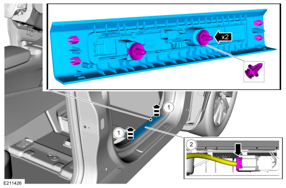
Remove the front door scuff plate trim panel.
-
Release the clips and remove the front door scuff plate trim panel.
-
If equipped, disconnect the electrical connector and remove the front door scuff plate trim panel.
-
Release the clips and remove the front door scuff plate trim panel.
 |
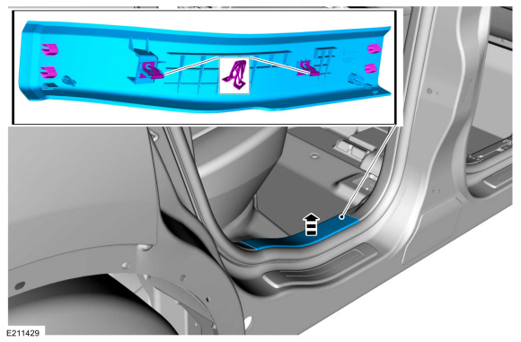
-
Release the clips and remove the rear door scuff plate trim panel.
 |
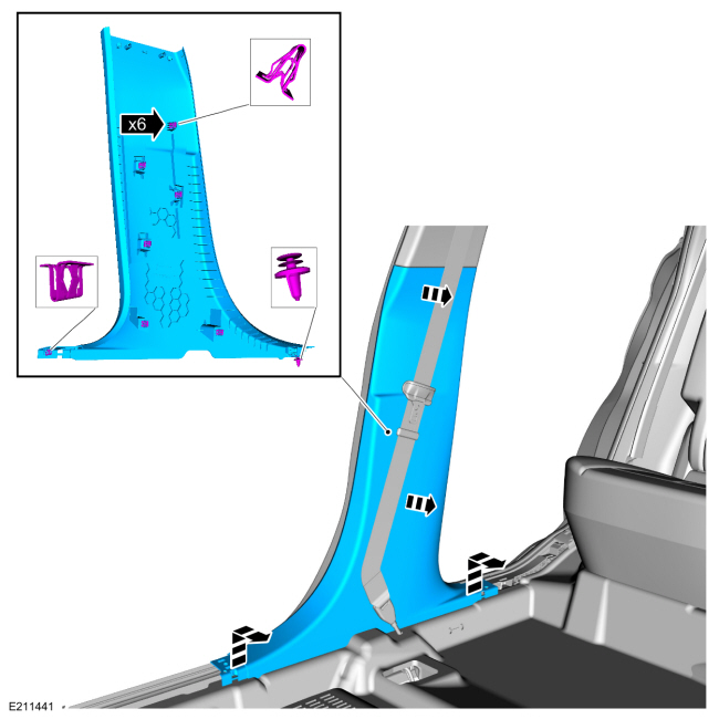
-
Release the clips and remove the lower B-pillar trim panel.
 |
Upper
-
Depower the SRS .
Refer to: Supplemental Restraint System (SRS) Depowering (501-20 Supplemental Restraint System) .
-
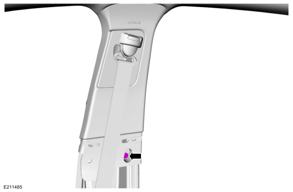
NOTE: Follow the unique instructions or graphic for this step in the installation.
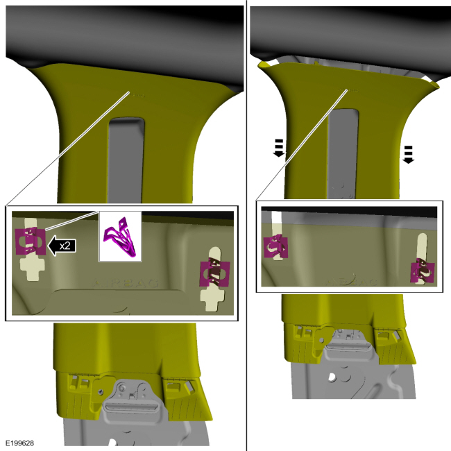
Disconnect the safety belt from the anchor and pretensioner.
-
Insert the special tool.
Install Special Service Tool: 501-403 Tool, Pretensioner Quick Connect.
-
NOTE: Allow insertion of the second tool to push the first tool from the mini-buckle.
Insert the second tool.
Install Special Service Tool: 501-403 Tool, Pretensioner Quick Connect.
-
Remove the second tool.
Remove Special Service Tool: 501-403 Tool, Pretensioner Quick Connect.
-
Disconnect the safety belt from the anchor and pretensioner and position aside.
-
Insert the special tool.
.jpg) |
-
Remove the upper B-pillar trim panel retainer.
Torque: 80 lb.in (9 Nm)
 |
-
Release the lower clip.
.jpg) |
-
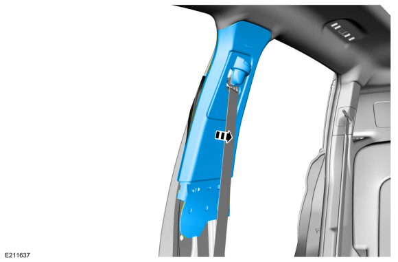
NOTICE: The trim panel must be positioned downward to allow the upper clips to release correctly. Failure to follow this direction may cause damage to the trim panel.
Slide the upper B-pillar trim panel down, aligning the clips to the slots in the sheet metal.
 |
-
Remove the upper B-pillar trim panel.
 |
Installation
-
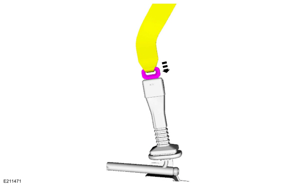
NOTE: During installation, make sure the safety belt webbing is not twisted and the safety belts and buckles are accessible to the occupants.
To install, reverse the removal procedure.
-
NOTE: During the latching sequence, tongue insertion should not be hindered by excessive effort and a click will be heard when the safety belt buckle latches the tongue. If the safety belt tongue cannot be inserted into the safety belt anchor and pretensioner, it will be necessary to reset the latch inside the safety belt anchor and pretensioner using the service tools.
Insert the safety belt into the anchor and pretensioner.
 |
-
Repower the SRS .
Refer to: Supplemental Restraint System (SRS) Repowering (501-20 Supplemental Restraint System) .
 A-Pillar Trim Panel. Removal and Installation
Special Tool(s) /
General Equipment
Flat Headed Screw Driver
Removal
NOTE:
Left hand (LH) shown, right hand (RH) similar.
Disconnect the tether clips from the A-pillar trim panel...
 C-Pillar Trim Panel. Removal and Installation
Removal
NOTE:
RH side shown, LH side similar.
NOTE:
Removal steps in this procedure may contain installation details.
Remove the loadspace trim panel...
Other information:
Lincoln Nautilus 2018-2026 Owners Manual: Rear Occupant Alert System Limitations. Switching Rear Occupant Alert System On and Off
Rear Occupant Alert System Limitations The system does not detect the presence of objects or passengers in the rear seat. It monitors when rear doors are opened and closed. Note: It is possible to receive an alert when there is no rear seat occupant, but alert conditions are met...
Lincoln Nautilus 2018-2026 Service Manual: Tire Pressure Monitoring System (TPMS) Sensor Location Calibration. General Procedures
Special Tool(s) / General Equipment 204-D081A (204-D081) Tire Pressure Monitor (TPMS) Ford Diagnostic Equipment Programming NOTE: The TPMS can be placed into learn mode using a diagnostic scan tool or manually where a diagnostic scan tool is not available...
Categories
- Manuals Home
- 1st Generation Nautilus Owners Manual
- 1st Generation Nautilus Service Manual
- Fuel Quality
- Massage Seats
- Programming the Garage Door Opener to Your Garage Door Opener Motor
- New on site
- Most important about car
Replacing the Rear Wiper Blades
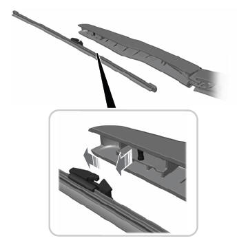
Note: Do not hold the wiper blade to lift the wiper arm.
Remove the wiper blade.