Lincoln Nautilus: Body Closures / Front Door Alignment. General Procedures
Lincoln Nautilus 2018-2026 Service Manual / Body and Paint / Body and Paint / Body Closures / Front Door Alignment. General Procedures
Inspection
NOTE: Removal steps in this procedure may contain installation details.
NOTE: LH side shown, RH side similar.
-
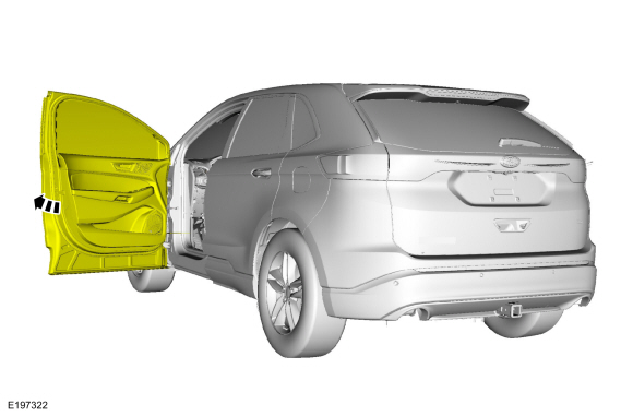
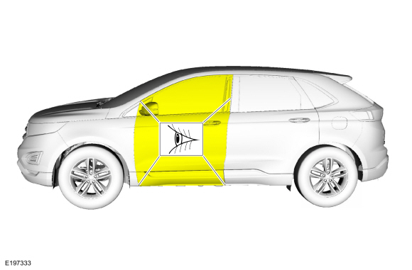
Inspect the front door-to-body dimensions.
Refer to: Body and Frame (501-26 Body Repairs - Vehicle Specific Information and Tolerance Checks, Description and Operation).
Adjustment
All alignments
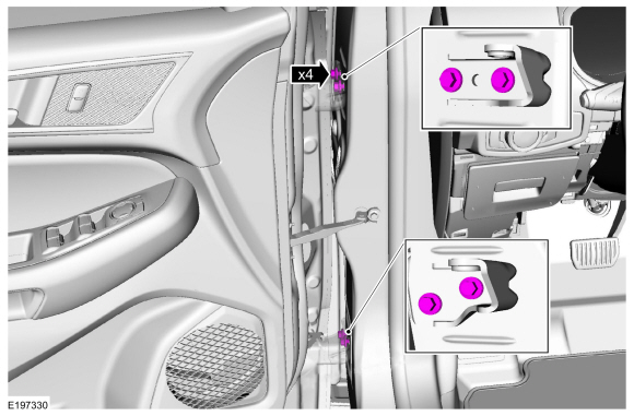
-
Open the door.
 |
-
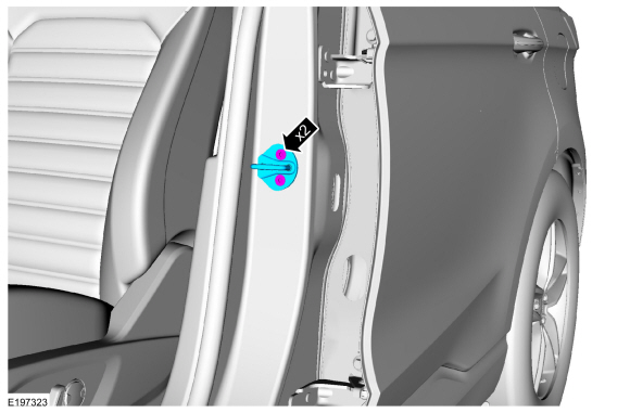
Remove the bolts and the striker assembly.
Torque: 18 lb.ft (25 Nm)
 |
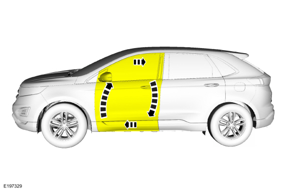
Front door in and out, up and down alignment
-
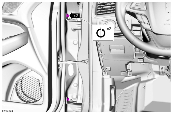
Loosen the bolts to permit movement of the door.
Loosen:
: 2 turn(s)
 |
-
Adjust the door to specification.
Refer to: Body and Frame (501-26 Body Repairs - Vehicle Specific Information and Tolerance Checks, Description and Operation).
 |
-
Tighten the bolts.
Torque: 35 lb.ft (48 Nm)
.jpg) |
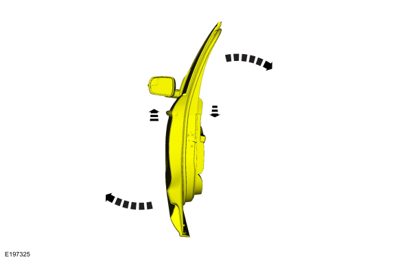
Front door fore, aft and tilt alignment
-
Loosen the bolts to permit movement of the door.
Loosen:
: 2 turn(s)
 |
-
Carefully close the door.
.jpg) |
-
Adjust the door to specification.
Refer to: Body and Frame (501-26 Body Repairs - Vehicle Specific Information and Tolerance Checks, Description and Operation).
 |
-
Carefully open the door.
|
-
Tighten the bolts.
Torque: 22 lb.ft (30 Nm)
 |
All alignments
-
Install the striker assembly.
Torque: 18 lb.ft (25 Nm)
|
-
Inspect the body-to-front door dimensions.
Refer to: Body and Frame (501-26 Body Repairs - Vehicle Specific Information and Tolerance Checks, Description and Operation).
 |
 Body Closures. Diagnosis and Testing
DTC Charts
Diagnostics in this manual assume a certain skill level and knowledge of Ford-specific diagnostic practices. REFER to: Diagnostic Methods (100-00 General Information, Description and Operation)...
 Hood Alignment. General Procedures
Inspection
NOTE:
Removal steps in this procedure may contain installation details.
Inspect the hood-to-body dimensions.
Refer to: Body and Frame (501-26 Body Repairs - Vehicle Specific Information and Tolerance Checks, Description and Operation)...
Other information:
Lincoln Nautilus 2018-2026 Owners Manual: Feature Bar
The bar is on the bottom of the display and allows you to access vehicle features. Select to use the radio, a USB, a media player or a Bluetooth device. Select to adjust climate settings. Select to make calls and access the phonebook on your cell phone...
Lincoln Nautilus 2018-2026 Service Manual: Brake System Pressure Bleeding. General Procedures
Special Tool(s) / General Equipment Brake/Clutch System Pressure Bleeder/Filler Fluid Container Bleeding All vehicles NOTICE: If the fluid is spilled on the paintwork, the affected area must be immediately washed down with cold water...
Categories
- Manuals Home
- 1st Generation Nautilus Owners Manual
- 1st Generation Nautilus Service Manual
- Folding the Exterior Mirrors - Vehicles With: Manual Folding Mirrors. Folding the Exterior Mirrors - Vehicles With: Power Folding Mirrors
- Programming the Garage Door Opener to Your Garage Door Opener Motor
- Switching the Lane Keeping System On and Off. Switching the Lane Keeping System Mode
- New on site
- Most important about car
Replacing the Rear Wiper Blades
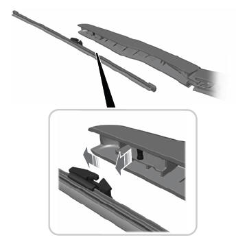
Note: Do not hold the wiper blade to lift the wiper arm.
Remove the wiper blade.Copyright © 2026 www.linautilus.com