Lincoln Nautilus: Exterior Lighting / Headlamp Control Module (HCM). Removal and Installation
Removal
NOTE: Removal steps in this procedure may contain installation details.
-
NOTE: This step is only necessary if the HCM is being replaced.
NOTE: If installing a new module, it is necessary to upload the module configuration information to the scan tool prior to removing the module. This information must be downloaded into the new module after installation.
NOTE: If the HCM did not respond to the diagnostic scan tool, As-Built Data may need to be entered as part of the repair.
Using a diagnostic scan tool, begin the PMI process for the HCM following the on-screen instructions.
-
Remove the push pins, disconnect the electrical connector and remove the RH dash insulator panel.
.jpg) |
-
Remove the headlamp control module.
-
Remove the headlamp control module bracket bolts and the headlamp control module.
Torque: 80 lb.in (9 Nm)
-
Disconnect the headlamp control module electrical connector.
-
Remove the headlamp control module bracket bolts and the headlamp control module.
.jpg) |
Installation
-
To install, reverse the removal procedure.
-
Using a diagnostic scan tool, complete the PMI process for the HCM following the on-screen instructions.
 Headlamp Bulb. Removal and Installation
Removal
Remove the headlamp assembly.
Refer to: Headlamp Assembly (417-01 Exterior Lighting, Removal and Installation).
Remove the screws and position the ballast...
 Headlamp Leveling Module. Removal and Installation
Removal
NOTE:
Removal steps in this procedure may contain installation details.
NOTE:
If installing a new module, it is necessary to
upload the module configuration information to the scan tool prior to
removing the module...
Other information:
Lincoln Nautilus 2018-2026 Owners Manual: Auto Mode
Switching Auto Mode On and Off Press the button to switch auto mode on. Repeatedly press the button to adjust auto mode. The system adjusts the blower motor speed, air distribution, air conditioning operation, and outside or recirculated air to reach and maintain the temperature you have set...
Lincoln Nautilus 2018-2026 Service Manual: Subwoofer and Amplifier Unit. Removal and Installation
Removal NOTE: Removal steps in this procedure may contain installation details. All vehicles Remove the RH loadspace trim panel. Refer to: Loadspace Trim Panel (501-05 Interior Trim and Ornamentation) . Subwoofer with integral amplifier Remove the bolts and the subwoofer assembly...
Categories
- Manuals Home
- 1st Generation Nautilus Owners Manual
- 1st Generation Nautilus Service Manual
- Power Outlet - Vehicles With: 110V Power Outlet
- Opening the Liftgate
- Locating the Pre-Collision Assist Sensors
- New on site
- Most important about car
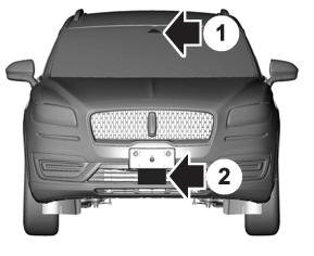
Locating the Pre-Collision Assist Sensors

If a message regarding a blocked sensor or camera appears in the information display, something is obstructing the radar signals or camera images. The radar sensor is behind the fascia cover in the center of the lower grille. With a blocked sensor or camera, the system may not function, or performance may reduce. See Pre-Collision Assist – Information Messages.
