Lincoln Nautilus: Wipers and Washers / Wipers and Washers. Diagnosis and Testing
DTC Chart: BCM
Diagnostics in this manual assume a certain skill level and knowledge of Ford-specific diagnostic practices.
REFER to: Diagnostic Methods (100-00 General Information, Description and Operation).
BCM
DTC Chart
|
DTC
|
Description
|
Action
|
|
B130F:12
|
Run Accessory Control: Circuit Short To Battery
|
GO to Pinpoint Test A
|
|
B130F:14
|
Run Accessory Control: Circuit Short To Ground or Open
|
-
If the windshield wipers are inoperative, GO to Pinpoint Test A
-
If the windshield wipers operate with the ignition off, GO to Pinpoint Test D
|
|
All other Diagnostic Trouble Codes (DTCs)
|
-
|
REFER to: Body Control Module (BCM) (419-10 Multifunction Electronic Modules, Diagnosis and Testing).
|
DTC Chart: SCCM
Diagnostics in this manual assume a certain skill level and knowledge of Ford-specific diagnostic practices.
REFER to: Diagnostic Methods (100-00 General Information, Description and Operation).
SCCM
DTC Chart
|
DTC
|
Description
|
Action
|
|
B1008:09
|
Wiper Mode Switch: Component Failure
|
-
INSTALL a new wiper/washer switch.
REFER to: Steering Column
Multifunction Switch RH (211-05 Steering Wheel and Column Electrical
Components, Removal and Installation).
-
CLEAR the DTC and repeat the self-test. If DTC B1008:09 is retrieved again, INSTALL a new SCCM .
REFER
to: Steering Column Control Module (SCCM) (211-05 Steering Wheel and
Column Electrical Components, Removal and Installation).
REFER to: Steering Column Control Module (SCCM) - Vehicles With:
Adaptive Steering (211-05 Steering Wheel and Column Electrical
Components, Removal and Installation).
|
|
B1051:09
|
Front Washer Switch: Component Failure
|
-
INSTALL a new wiper/washer switch.
REFER to: Steering Column
Multifunction Switch RH (211-05 Steering Wheel and Column Electrical
Components, Removal and Installation).
-
CLEAR the DTC and repeat the self-test. If DTC B1008:09 is retrieved again, INSTALL a new SCCM .
REFER
to: Steering Column Control Module (SCCM) (211-05 Steering Wheel and
Column Electrical Components, Removal and Installation).
REFER to: Steering Column Control Module (SCCM) - Vehicles With:
Adaptive Steering (211-05 Steering Wheel and Column Electrical
Components, Removal and Installation).
|
|
B1052:09
|
Rear Washer Switch: Component Failure
|
-
INSTALL a new wiper/washer switch.
REFER to: Steering Column
Multifunction Switch RH (211-05 Steering Wheel and Column Electrical
Components, Removal and Installation).
-
CLEAR the DTC and repeat the self-test. If DTC B1008:09 is retrieved again, INSTALL a new SCCM .
REFER
to: Steering Column Control Module (SCCM) (211-05 Steering Wheel and
Column Electrical Components, Removal and Installation).
REFER to: Steering Column Control Module (SCCM) - Vehicles With:
Adaptive Steering (211-05 Steering Wheel and Column Electrical
Components, Removal and Installation).
|
|
B10AD:02
|
Rain Sensor: General Signal Failure
|
GO to Pinpoint Test F
|
|
B10AD:08
|
Rain Sensor: Bus Signal / Message Failure
|
GO to Pinpoint Test F
|
|
B10AD:49
|
Rain Sensor: Internal Electronic Failure
|
INSTALL a new rain sensor.
REFER to: Rain Sensor (501-16 Wipers and Washers, Removal and Installation).
|
|
B10AD:55
|
Rain Sensor: Not Configured
|
PERFORM the PMI for the SCCM using As-Built data.
|
|
B1131:02
|
Wiper motor module: General Signal Failure
|
-
If the wipers are inoperative, or no symptom is present, GO to Pinpoint Test A
-
If the wipers are always on, GO to Pinpoint Test D
|
|
B1131:08
|
Wiper motor module: Bus Signal / Message Failure
|
GO to Pinpoint Test B
|
|
B1131:11
|
Wiper motor module: Circuit Short To Ground
|
GO to Pinpoint Test B
|
|
B1131:49
|
Wiper motor module: Internal Electronic Failure
|
INSTALL a new windshield wiper motor.
REFER to: Windshield Wiper Motor (501-16 Wipers and Washers, Removal and Installation).
|
|
B1131:9A
|
Wiper motor module: Component or System Operating Conditions
|
DIAGNOSE the symptom present with the
wiper/washer system. REFER to the Symptom Chart in this section.
|
|
B1131:55
|
Wiper motor module: Not Configured
|
CARRY OUT the PMI for the SCCM using as built data.
|
|
B12F7:09
|
Single Wipe Switch: Component Failure
|
-
INSTALL a new wiper/washer switch.
REFER to: Steering Column
Multifunction Switch RH (211-05 Steering Wheel and Column Electrical
Components, Removal and Installation).
-
CLEAR the DTC and repeat the self-test. If DTC B1008:09 is retrieved again, INSTALL a new SCCM .
REFER
to: Steering Column Control Module (SCCM) (211-05 Steering Wheel and
Column Electrical Components, Removal and Installation).
REFER to: Steering Column Control Module (SCCM) - Vehicles With:
Adaptive Steering (211-05 Steering Wheel and Column Electrical
Components, Removal and Installation).
|
|
All other Diagnostic Trouble Codes (DTCs)
|
-
|
REFER to: Steering Wheel and Column Electrical Components (211-05
Steering Wheel and Column Electrical Components, Diagnosis and Testing).
|
Symptom Chart
Symptom Chart: Wiper and Washer
Diagnostics in this manual assume a certain skill level and knowledge of Ford-specific diagnostic practices.
REFER to: Diagnostic Methods (100-00 General Information, Description and Operation).
Symptom Chart
|
Condition
|
Actions
|
|
Wiper blade performance concerns - poor cleaning, streaking, or chatter
|
|
|
All windshield wiper modes are inoperative
|
|
|
The intermittent and/or low speed windshield wipers are inoperative
|
|
|
The high speed windshield wipers are inoperative
|
|
|
The windshield wipers stay on continuously
|
|
|
The windshield wipers do not operate correctly in the intermittent mode
|
|
|
The rain sensitive wiper feature is inoperative
|
|
|
The rain sensitive wipers have erratic/inconsistent operation
|
|
|
The rain sensitive wipers are too sensitive/not sensitive enough to moisture
|
|
|
The windshield wipers do not park at the correct position
|
|
|
The windshield washer is inoperative
|
|
|
The windshield washer is always on
|
|
|
One or more rear window wiper modes are inoperative
|
|
|
The rear window wiper stays on continuously
|
|
|
The rear window wiper does not park at the correct position
|
-
CHECK the rear window wiper sweep pattern and make sure it is correct.
-
If the pattern is incorrect, ADJUST the rear window wiper arm.
REFER to: Windshield Wiper Pivot Arm (501-16 Wipers and Washers, Removal and Installation).
-
If the pattern is correct, INSTALL a new rear window wiper motor.
REFER to: Rear Window Wiper Motor (501-16 Wipers and Washers, Removal and Installation).
|
|
The rear window washer is inoperative
|
|
|
The rear window washer is always on
|
|
|
One or both headlamp washers are inoperative
|
|
|
The headlamp washers are always on
|
|
|
The front camera washer is inoperative
|
|
|
The heated wiper park feature is inoperative
|
|
|
The heated wiper park feature is always on
|
|
Pinpoint Tests
All Windshield Wiper Modes Are Inoperative
Refer to Wiring Diagrams Cell 81 for schematic and connector information.
Normal Operation and Fault Conditions
REFER to: Wipers and Washers - System Operation and Component
Description (501-16 Wipers and Washers, Description and Operation).
BCM
DTC Fault Trigger Conditions
|
DTC
|
Description
|
Fault Trigger Conditions
|
|
B130F:12
|
Run Accessory Control: Circuit Short To Battery
|
Sets when the BCM detects a short to voltage from the wiper relay control circuit.
|
|
B130F:14
|
Run Accessory Control: Circuit Short To Ground or Open
|
Sets when the BCM detects an open or short to ground from the wiper relay control circuit.
|
SCCM
DTC Fault Trigger Conditions
|
DTC
|
Description
|
Fault Trigger Conditions
|
|
B1131:02
|
Wiper motor module: General Signal Failure
|
Sets when the input to the windshield wiper
motor from the fail-safe circuit does not match the requested input from
the SCCM .
|
Possible Causes
-
Fuse
-
Wiring, terminals or connectors
-
BJB
-
Windshield wiper motor
-
SCCM
-
BCM
Visual Inspection and Diagnostic Pre-checks
-
Inspect BJB fuses 3 (15A) and 75 (25A) and make sure they are OK.
PINPOINT TEST A: ALL WINDSHIELD WIPER MODES ARE INOPERATIVE
| NOTICE:
Use the correct probe adapter(s) when making
measurements. Failure to use the correct probe adapter(s) may damage the
connector.
|
| A1 CHECK FOR BCM (BODY CONTROL MODULE)
DTC (DIAGNOSTIC TROUBLE CODE)
B130F:12, B130F:14 OR SCCM (STEERING COLUMN CONTROL MODULE)
DTC (DIAGNOSTIC TROUBLE CODE)
B1131:02 |
-
Using a diagnostic scan tool, perform the BCM self-test.
-
Using a diagnostic scan tool, perform the SCCM self-test.
Is DTC B130F:12, B130F:14 or B1131:02 present?
| Yes |
For DTC B130F:12, GO to A2
For DTC B130F:14, GO to A4
For DTC B1131:02, GO to A11
|
|
| A2 CHECK THE WIPER RELAY CONTROL CIRCUIT FOR A SHORT TO VOLTAGE |
-
Measure:
|
Positive Lead
|
Measurement / Action
|
Negative Lead
|
|
C2280C-24
|

|
Ground
|
Is any voltage present?
|
| A3 ISOLATE THE SHORT TO VOLTAGE IN THE WIPER RELAY CONTROL |
-
Measure:
|
Positive Lead
|
Measurement / Action
|
Negative Lead
|
|
C1035B-37
|
|
Ground
|
Is any voltage present?
|
| A4 CHECK THE WIPER RELAY CONTROL CIRCUIT FOR A SHORT TO GROUND |
-
Measure:
|
Positive Lead
|
Measurement / Action
|
Negative Lead
|
|
C2280C-24
|

|
Ground
|
Is the resistance greater than 10,000 ohms?
|
| A5 CHECK THE WIPER RELAY CONTROL CIRCUIT FOR AN OPEN |
-
Measure:
|
Positive Lead
|
Measurement / Action
|
Negative Lead
|
|
C1035B-37
|
|
C2280C-24
|
Is the resistance less than 3 ohms?
|
| A6 CHECK BCM WIPER RELAY CONTROL CIRCUIT |
|
NOTICE:
This pinpoint test step uses a test lamp to simulate
normal circuit loads. Use only a Rotunda Test Lamp (SGT27000) or
250-300mA incandescent bulb test lamp. To avoid connector terminal
damage, use the Rotunda Flex Probe kit for the test lamp probe
connection to the vehicle. Do not use the test lamp probe directly on
any connector.
-
Connect:
Click to display connectors
|
Positive Lead
|
Measurement / Action
|
Negative Lead
|
|
C1035B-37
|

|
Positive battery terminal
|
Does the test lamp illuminate when the ignition is ON, and turn off when the ignition is OFF?
|
| A7 CHECK THE INPUT TO THE SCCM (STEERING COLUMN CONTROL MODULE)
|
-
Using a diagnostic scan tool, view the SCCM Parameter Identifications (PIDs).
-
Using a diagnostic scan tool, view the following SCCM wiper/washer switch Parameter Identifications (PIDs):
-
WIPE_SINGLE (Single Wipe Stroke)
-
F_WASH_SW (Washer Switch (Front))
-
F_WIP_INT_D1 (Front Wiper Intermittent Data 1)
-
F_WIP_INT_D2 (Front Wiper Intermittent Data 2)
-
F_WIP_INT_D3 (Front Wiper Intermittent Data 3)
-
F_WIP_INT_D4 (Front Wiper Intermittent Data 4)
-
F_WIP_INT_D5 (Front Wiper Intermittent Data 5)
-
F_WIP_INT_D6 (Front Wiper Intermittent Data 6)
-
F_WIP_SLO_SW (Front Wiper Command Low Speed)
-
F_WIPE_FAST_SW (Front Wiper Command High Speed)
-
Cycle the wiper/washer switch from off to the high speed setting and then back to off.
Do the Parameter Identifications (PIDs) correspond correctly with each setting selection?
| No |
INSTALL a new wiper/washer switch.
REFER to: Steering Column
Multifunction Switch RH (211-05 Steering Wheel and Column Electrical
Components, Removal and Installation). TEST the system for normal
operation. If the concern is still present, GO to A14
|
|
| A8 CHECK FOR VOLTAGE TO THE WINDSHIELD WIPER MOTOR |
-
Disconnect Windshield Wiper Motor C1655
.
-
Measure:
Click to display connectors
|
Positive Lead
|
Measurement / Action
|
Negative Lead
|
|
C1655-8
|
|
Ground
|
Is the voltage greater than 11 volts?
| No |
VERIFY the BJB fuse 75 (25A) is OK. If OK, GO to A9
If not OK, REFER to the Wiring Diagrams manual to identify the possible causes of the circuit short.
|
|
| A9 CHECK THE WIPER RELAY VOLTAGE SUPPLY CIRCUIT FOR AN OPEN |
-
Measure:
|
Positive Lead
|
Measurement / Action
|
Negative Lead
|
|
C1035B-49
|
|
C1655-8
|
Is the voltage greater than 11 volts?
|
| A10 CHECK THE WINDSHIELD WIPER MOTOR GROUND CIRCUIT FOR AN OPEN |
-
Measure:
Click to display connectors
|
Positive Lead
|
Measurement / Action
|
Negative Lead
|
|
C1655-6
|
|
Ground
|
Is the resistance less than 3 ohms?
|
| A11 CHECK THE FAIL-SAFE HIGH SPEED WIPER GROUND CIRCUIT CONTROL |
-
Disconnect Windshield Wiper Motor C1655
.
-
Place the wiper/washer switch to the high speed setting.
-
Measure:
Click to display connectors
|
Positive Lead
|
Measurement / Action
|
Negative Lead
|
|
C1655-1
|
|
Ground
|
Is the resistance less than 3 ohms?
|
| A12 CHECK THE FAIL-SAFE HIGH SPEED WIPER GROUND CIRCUIT FOR AN OPEN |
|
NOTE:
If steps A2-A10 did not identify the cause of the
concern, a double fault is present. After the fail-safe ground is
diagnosed and repaired, it is necessary to check all operation modes and
diagnose any symptom still present.
-
Measure:
Click to display connectors
|
Positive Lead
|
Measurement / Action
|
Negative Lead
|
|
C1655-1
|
|
C226A-2
|
Is the resistance less than 3 ohms?
| Yes |
INSTALL a new wiper/washer switch.
REFER to: Steering Column
Multifunction Switch RH (211-05 Steering Wheel and Column Electrical
Components, Removal and Installation). TEST the system for normal
operation. If the concern is still present, GO to A14
|
|
| A13 CHECK FOR CORRECT WINDSHIELD WIPER MOTOR OPERATION |
-
Disconnect and inspect the windshield wiper motor connector.
-
Repair:
-
corrosion (install new connector or terminal - clean module pins)
-
damaged or bent pins - install new terminals/pins
-
pushed-out pins - install new pins as necessary
-
Reconnect the windshield wiper motor connector. Make sure it seats and latches correctly.
-
Operate the system and determine if the concern is still present.
Is the concern still present?
| Yes |
CHECK OASIS for any applicable Technical Service Bulletins (TSBs). If a
TSB exists for this concern, DISCONTINUE this test and FOLLOW the TSB
instructions. If no Technical Service Bulletins (TSBs) address this
concern, INSTALL a new windshield wiper motor.
REFER to: Rear Window Wiper Motor (501-16 Wipers and Washers, Removal and Installation).
|
| No |
The system is operating correctly at this time. The
concern may have been caused by a loose or corroded connector. ADDRESS
the root cause of any connector or pin issues.
|
|
| A14 CHECK FOR CORRECT SCCM (STEERING COLUMN CONTROL MODULE)
OPERATION |
-
Disconnect and inspect all the SCCM connectors:
-
Repair:
-
corrosion (install new connector or terminals – clean module pins)
-
damaged or bent pins – install new terminals/pins
-
pushed-out pins – install new pins as necessary
-
Reconnect the SCCM connectors. Make sure they seat and latch correctly.
Is the concern still present?
| Yes |
CHECK OASIS for any applicable Technical Service Bulletins (TSBs). If a
TSB exists for this concern, DISCONTINUE this test and FOLLOW the TSB
instructions. If no Technical Service Bulletins (TSBs) address this
concern, INSTALL a new SCCM .
REFER to: Steering Column Control
Module (SCCM) (211-05 Steering Wheel and Column Electrical Components,
Removal and Installation).
REFER to: Steering Column Control Module (SCCM) - Vehicles With:
Adaptive Steering (211-05 Steering Wheel and Column Electrical
Components, Removal and Installation).
|
| No |
The system is operating correctly at this time. The
concern may have been caused by module connections. ADDRESS the root
cause of any connector or pin issues.
|
|
| A15 CHECK FOR CORRECT BCM (BODY CONTROL MODULE)
OPERATION |
-
Disconnect and inspect all the BCM connectors:
-
Repair:
-
corrosion (install new connector or terminals – clean module pins)
-
damaged or bent pins – install new terminals/pins
-
pushed-out pins – install new pins as necessary
-
Reconnect the BCM connectors. Make sure they seat and latch correctly.
Is the concern still present?
| Yes |
INSTALL a new BCM. Refer to the appropriate Removal and Installation procedure in Section 419-10.
|
| No |
The system is operating correctly at this time. The
concern may have been caused by module connections. ADDRESS the root
cause of any connector or pin issues.
|
|
The Intermittent And/Or Low Speed Windshield Wipers Are Inoperative
Refer to Wiring Diagrams Cell 81 for schematic and connector information.
Normal Operation and Fault Conditions
REFER to: Wipers and Washers - System Operation and Component
Description (501-16 Wipers and Washers, Description and Operation).
SCCM
DTC Fault Trigger Conditions
|
DTC
|
Description
|
Fault Trigger Conditions
|
|
B1131:08
|
Wiper motor module: Bus Signal / Message Failure
|
Sets when the SCCM detects a communication fault with the windshield wiper motor over the LIN .
|
|
B1131:11
|
Wiper motor module: Circuit Short to Ground
|
Sets when the SCCM detects a short to ground from the windshield wiper motor LIN circuit.
|
Possible Causes
-
Wiring, terminals or connectors
-
Wiper/washer switch
-
Windshield wiper motor
-
Rain sensor
-
SCCM
Visual Inspection and Diagnostic Pre-checks
-
Inspect the wiper/washer switch for damage.
PINPOINT TEST B: THE INTERMITTENT AND/OR LOW SPEED WINDSHIELD WIPERS ARE INOPERATIVE
| NOTICE:
Use the correct probe adapter(s) when making
measurements. Failure to use the correct probe adapter(s) may damage the
connector.
|
| NOTE:
It may be necessary to disconnect and then reconnect the battery after the repair to enable the wiper operation.
|
| B1 CHECK THE HIGH SPEED WIPER OPERATION |
-
Place the wiper/washer switch to the high speed
setting and observe the windshield wipers. Place the wiper/washer switch
to the off setting.
Do the windshield wipers operate with the wiper/washer switch in the high speed setting?
|
| B2 CHECK THE LOW SPEED WIPER OPERATION |
-
Place the wiper/washer switch to the low speed
setting and observe the windshield wipers. Place the wiper/washer switch
to the off setting.
Do the windshield wipers operate with the wiper/washer switch in the low speed setting?
| Yes |
If not equipped with a rain sensor, GO to Pinpoint Test E
If equipped with a rain sensor, GO to Pinpoint Test F
|
|
| B3 CHECK THE INPUT TO THE SCCM (STEERING COLUMN CONTROL MODULE)
|
-
Using a diagnostic scan tool, view the SCCM Parameter Identifications (PIDs).
-
Using a diagnostic scan tool, view the SCCM F_WIP_SLO_SW PID .
-
Place the wiper/washer switch to the low speed setting.
Does the PID indicate the wiper/washer switch is in the low speed setting?
| Yes |
If equipped with a rain sensor, GO to B4
If not equipped with a rain sensor, GO to B5
|
| No |
INSTALL a new wiper/washer switch.
REFER to: Steering Column
Multifunction Switch RH (211-05 Steering Wheel and Column Electrical
Components, Removal and Installation). TEST the system for normal
operation. If the concern is still present, GO to B9
|
|
| B4 ISOLATE THE RAIN SENSOR |
-
Disconnect Rain Sensor C914
.
-
Place the wiper/washer switch to the low speed
setting and observe the windshield wipers. Place the wiper/washer switch
to the off setting.
Do the windshield wipers operate with the wiper/washer switch in the low speed setting?
| Yes |
INSTALL a new rain sensor.
REFER to: Rain Sensor (501-16 Wipers and Washers, Removal and Installation).
|
|
| B5 CHECK THE LIN (LOCAL INTERCONNECT NETWORK)
CIRCUIT FOR A SHORT TO VOLTAGE |
-
Disconnect Windshield Wiper Motor C1655
.
-
Measure:
Click to display connectors
|
Positive Lead
|
Measurement / Action
|
Negative Lead
|
|
C1655-4
|
|
Ground
|
Is any voltage present?
|
| B6 CHECK THE LIN (LOCAL INTERCONNECT NETWORK)
CIRCUIT FOR A SHORT TO GROUND |
-
Measure:
Click to display connectors
|
Positive Lead
|
Measurement / Action
|
Negative Lead
|
|
C1655-4
|
|
Ground
|
Is the resistance greater than 10,000 ohms?
|
| B7 CHECK THE LIN (LOCAL INTERCONNECT NETWORK)
CIRCUIT FOR AN OPEN |
-
Measure:
Click to display connectors
|
Positive Lead
|
Measurement / Action
|
Negative Lead
|
|
C1655-4
|
|
C226A-8
|
Is the resistance less than 3 ohms?
|
| B8 CHECK FOR CORRECT WINDSHIELD WIPER MOTOR OPERATION |
-
Disconnect and inspect the windshield wiper motor connector.
-
Repair:
-
corrosion (install new connector or terminal - clean module pins)
-
damaged or bent pins - install new terminals/pins
-
pushed-out pins - install new pins as necessary
-
Reconnect the windshield wiper motor connector. Make sure it seats and latches correctly.
-
Operate the system and determine if the concern is still present.
Is the concern still present?
| Yes |
CHECK OASIS for any applicable Technical Service Bulletins (TSBs). If a
TSB exists for this concern, DISCONTINUE this test and FOLLOW the TSB
instructions. If no Technical Service Bulletins (TSBs) address this
concern, INSTALL a new windshield wiper motor.
REFER to: Rear Window
Wiper Motor (501-16 Wipers and Washers, Removal and Installation). TEST
the system for normal operation. If the concern is still present, GO to
B9
|
| No |
The system is operating correctly at this time. The
concern may have been caused by a loose or corroded connector. ADDRESS
the root cause of any connector or pin issues.
|
|
| B9 CHECK FOR CORRECT SCCM (STEERING COLUMN CONTROL MODULE)
OPERATION |
-
Disconnect and inspect all the SCCM connectors.
-
Repair:
-
corrosion (install new connector or terminal - clean module pins)
-
damaged or bent pins - install new terminals/pins
-
pushed-out pins - install new pins as necessary
-
Reconnect the SCCM connectors. Make sure they seat and latch correctly.
-
Operate the system and determine if the concern is still present.
Is the concern still present?
| Yes |
CHECK OASIS for any applicable Technical Service Bulletins (TSBs). If a
TSB exists for this concern, DISCONTINUE this test and FOLLOW the TSB
instructions. If no Technical Service Bulletins (TSBs) address this
concern, INSTALL a new SCCM .
REFER to: Steering Column Control
Module (SCCM) (211-05 Steering Wheel and Column Electrical Components,
Removal and Installation).
REFER to: Steering Column Control Module (SCCM) - Vehicles With:
Adaptive Steering (211-05 Steering Wheel and Column Electrical
Components, Removal and Installation).
|
| No |
The system is operating correctly at this time. The
concern may have been caused by a loose or corroded connector. ADDRESS
the root cause of any connector or pin issues.
|
|
The High Speed Windshield Wipers Are Inoperative
Normal Operation and Fault Conditions
REFER to: Wipers and Washers - System Operation and Component
Description (501-16 Wipers and Washers, Description and Operation).
Possible Causes
-
Windshield wiper motor
-
Wiper/washer switch
-
SCCM
PINPOINT TEST C: THE HIGH SPEED WINDSHIELD WIPERS ARE INOPERATIVE
| C1 CHECK THE INPUT TO THE SCCM (STEERING COLUMN CONTROL MODULE)
|
-
Using a diagnostic scan tool, view the SCCM Parameter Identifications (PIDs).
-
Using a diagnostic scan tool, view the SCCM F_WIPE_FAST_SW PID .
-
Place the wiper/washer switch to the high speed setting.
Does the PID indicate the wiper/washer switch is in the high speed setting?
| Yes |
INSTALL a new windshield wiper motor.
REFER to: Steering Column
Multifunction Switch RH (211-05 Steering Wheel and Column Electrical
Components, Removal and Installation).
|
| No |
INSTALL a new wiper/washer switch.
REFER to: Steering Column
Multifunction Switch RH (211-05 Steering Wheel and Column Electrical
Components, Removal and Installation). TEST the system for normal
operation. If the concern is still present, INSTALL a new SCCM .
REFER
to: Steering Column Control Module (SCCM) (211-05 Steering Wheel and
Column Electrical Components, Removal and Installation).
REFER to: Steering Column Control Module (SCCM) - Vehicles With:
Adaptive Steering (211-05 Steering Wheel and Column Electrical
Components, Removal and Installation).
|
|
The Windshield Wipers Stay On Continuously
Refer to Wiring Diagrams Cell 81 for schematic and connector information.
Normal Operation and Fault Conditions
REFER to: Wipers and Washers - System Operation and Component
Description (501-16 Wipers and Washers, Description and Operation).
BCM
DTC Fault Trigger Conditions
|
DTC
|
Description
|
Fault Trigger Conditions
|
|
B130F:14
|
Run Accessory Control: Circuit Short To Ground or Open
|
Sets when the BCM detects a short to ground from the wiper relay control circuit.
|
SCCM
DTC Fault Trigger Conditions
|
DTC
|
Description
|
Fault Trigger Conditions
|
|
B1131:02
|
Wiper Motor Module: General Signal Failure
|
Sets when the input to the windshield wiper
motor from the fail-safe circuit does not match the requested input from
the SCCM .
|
Possible Causes
-
Wiring, terminals or connectors
-
Wiper/washer switch
-
BJB
-
Windshield wiper motor
-
SCCM
-
BCM
Visual Inspection and Diagnostic Pre-checks
-
Inspect the wiper/washer switch for damage.
PINPOINT TEST D: THE WINDSHIELD WIPERS STAY ON CONTINUOUSLY
| NOTICE:
Use the correct probe adapter(s) when making
measurements. Failure to use the correct probe adapter(s) may damage the
connector.
|
| D1 CHECK THE WINDSHIELD WIPER OPERATION WITH THE IGNITION OFF |
-
Observe the windshield wiper operation.
Do the windshield wipers operate with the ignition off?
|
| D2 CHECK THE WINDSHIELD WIPER OPERATION WITH THE SCCM (STEERING COLUMN CONTROL MODULE)
DISCONNECTED |
-
Observe the windshield wiper operation.
Do the windshield wipers continue to operate?
| No |
INSTALL a new wiper/washer switch.
REFER to: Steering Column
Multifunction Switch RH (211-05 Steering Wheel and Column Electrical
Components, Removal and Installation). TEST the system for normal
operation. If the concern is still present, GO to D8
|
|
| D3 CHECK THE HIGH SPEED FAIL-SAFE CIRCUIT FOR A SHORT TO GROUND |
-
Disconnect Windshield Wiper Motor C1655
.
-
Measure:
Click to display connectors
|
Positive Lead
|
Measurement / Action
|
Negative Lead
|
|
C1655-1
|
|
Ground
|
Is the resistance greater than 10,000 ohms?
|
| D4 CHECK FOR BCM (BODY CONTROL MODULE)
DTC (DIAGNOSTIC TROUBLE CODE)
B130F:14 |
-
Using a diagnostic scan tool, perform the BCM self-test.
Is DTC B130F:14 present?
|
| D5 CHECK THE WIPER RELAY CONTROL CIRCUIT FOR A SHORT TO GROUND |
-
Measure:
|
Positive Lead
|
Measurement / Action
|
Negative Lead
|
|
C2280C-24
|
|
Ground
|
Is the resistance greater than 10,000 ohms?
|
| D6 CHECK THE WINDSHIELD WIPER MOTOR VOLTAGE SUPPLY CIRCUIT FOR A SHORT TO VOLTAGE |
-
Measure:
|
Positive Lead
|
Measurement / Action
|
Negative Lead
|
|
C1035B-49
|
|
Ground
|
Is any voltage present?
|
| D7 CHECK FOR CORRECT WINDSHIELD WIPER MOTOR OPERATION |
-
Disconnect and inspect the windshield wiper motor connector.
-
Repair:
-
corrosion (install new connector or terminal - clean module pins)
-
damaged or bent pins - install new terminals/pins
-
pushed-out pins - install new pins as necessary
-
Reconnect the windshield wiper motor connector. Make sure it seats and latches correctly.
-
Operate the system and determine if the concern is still present.
Is the concern still present?
| Yes |
CHECK OASIS for any applicable Technical Service Bulletins (TSBs). If a
TSB exists for this concern, DISCONTINUE this test and FOLLOW the TSB
instructions. If no Technical Service Bulletins (TSBs) address this
concern, INSTALL a new windshield wiper motor.
REFER to: Windshield Wiper Motor (501-16 Wipers and Washers, Removal and Installation).
|
| No |
The system is operating correctly at this time. The
concern may have been caused by a loose or corroded connector. ADDRESS
the root cause of any connector or pin issues.
|
|
| D8 CHECK FOR CORRECT SCCM (STEERING COLUMN CONTROL MODULE)
OPERATION |
-
Disconnect and inspect all the SCCM connectors.
-
Repair:
-
corrosion (install new connector or terminal - clean module pins)
-
damaged or bent pins - install new terminals/pins
-
pushed-out pins - install new pins as necessary
-
Reconnect the SCCM connectors. Make sure they seat and latch correctly.
-
Operate the system and determine if the concern is still present.
Is the concern still present?
| Yes |
CHECK OASIS for any applicable Technical Service Bulletins (TSBs). If a
TSB exists for this concern, DISCONTINUE this test and FOLLOW the TSB
instructions. If no Technical Service Bulletins (TSBs) address this
concern, INSTALL a new SCCM .
REFER to: Steering Column Control
Module (SCCM) (211-05 Steering Wheel and Column Electrical Components,
Removal and Installation).
REFER to: Steering Column Control Module (SCCM) - Vehicles With:
Adaptive Steering (211-05 Steering Wheel and Column Electrical
Components, Removal and Installation).
|
| No |
The system is operating correctly at this time. The
concern may have been caused by a loose or corroded connector. ADDRESS
the root cause of any connector or pin issues.
|
|
| D9 CHECK FOR CORRECT BCM (BODY CONTROL MODULE)
OPERATION |
-
Disconnect and inspect all the BCM connectors.
-
Repair:
-
corrosion (install new connector or terminal - clean module pins)
-
damaged or bent pins - install new terminals/pins
-
pushed-out pins - install new pins as necessary
-
Reconnect the BCM connectors. Make sure they seat and latch correctly.
-
Operate the system and determine if the concern is still present.
Is the concern still present?
| Yes |
INSTALL a new BCM. Refer to the appropriate Removal and Installation procedure in Section 419-10.
|
| No |
The system is operating correctly at this time. The
concern may have been caused by a loose or corroded connector. ADDRESS
the root cause of any connector or pin issues.
|
|
The Windshield Wipers Do Not Operate Correctly In The Intermittent Mode
Normal Operation and Fault Conditions
REFER to: Wipers and Washers - System Operation and Component
Description (501-16 Wipers and Washers, Description and Operation).
Possible Causes
-
Wiper/washer switch
-
Windshield wiper motor
-
SCCM
Visual Inspection and Diagnostic Pre-checks
-
Inspect the wiper/washer switch for damage.
PINPOINT TEST E: THE WINDSHIELD WIPERS DO NOT OPERATE CORRECTLY IN THE INTERMITTENT MODE
| E1 VERIFY IF THE VEHICLE IS EQUIPPED WITH A RAIN SENSOR |
-
Inspect the vehicle for a rain sensor.
Is the vehicle equipped with a rain sensor?
|
| E2 VERIFY THE RAIN SENSITIVE WIPER FEATURE IS DISABLED IN THE VEHICLE MESSAGE CENTER |
-
Access the vehicle settings in the message center
using the steering wheel controls and check the rain sensitive feature
setting.
Is the rain sensitive feature enabled?
| Yes |
DISABLE the rain sensitive feature. INFORM the
customer how to disable the rain sensitive feature, activating the
intermittent setting.
|
|
| E3 CHECK THE LOW SPEED WIPER OPERATION |
-
Place the wiper/washer switch to the low speed
setting and observe the windshield wipers. Place the wiper/washer switch
to the off setting.
Do the low speed wipers operate when the low speed setting is selected?
|
| E4 CHECK THE INPUT FROM THE WIPER/WASHER SWITCH |
-
Using a diagnostic scan tool, view the SCCM Parameter Identifications (PIDs).
-
Using a diagnostic scan tool, view the following SCCM wiper/washer switch Parameter Identifications (PIDs):
-
F_WIP_INT_D1 (Front Wiper Intermittent Data 1)
-
F_WIP_INT_D2 (Front Wiper Intermittent Data 2)
-
F_WIP_INT_D3 (Front Wiper Intermittent Data 3)
-
F_WIP_INT_D4 (Front Wiper Intermittent Data 4)
-
F_WIP_INT_D5 (Front Wiper Intermittent Data 5)
-
F_WIP_INT_D6 (Front Wiper Intermittent Data 6)
-
Cycle the wiper/washer switch from off through each of the intermittent settings.
Do the Parameter Identifications (PIDs) correspond correctly with each setting selection?
| Yes |
INSTALL a new windshield wiper motor.
REFER to: Windshield Wiper Motor (501-16 Wipers and Washers, Removal and Installation).
|
| No |
INSTALL a new wiper/washer switch.
REFER to: Steering Column
Multifunction Switch RH (211-05 Steering Wheel and Column Electrical
Components, Removal and Installation). TEST the system for normal
operation. If the concern is still present, GO to E5
|
|
| E5 CHECK FOR CORRECT SCCM (STEERING COLUMN CONTROL MODULE)
OPERATION |
-
Disconnect and inspect all the SCCM connectors.
-
Repair:
-
corrosion (install new connector or terminal - clean module pins)
-
damaged or bent pins - install new terminals/pins
-
pushed-out pins - install new pins as necessary
-
Reconnect the SCCM connectors. Make sure they seat and latch correctly.
-
Operate the system and determine if the concern is still present.
Is the concern still present?
| Yes |
CHECK OASIS for any applicable Technical Service Bulletins (TSBs). If a
TSB exists for this concern, DISCONTINUE this test and FOLLOW the TSB
instructions. If no Technical Service Bulletins (TSBs) address this
concern, INSTALL a new SCCM .
REFER to: Steering Column Control
Module (SCCM) (211-05 Steering Wheel and Column Electrical Components,
Removal and Installation).
REFER to: Steering Column Control Module (SCCM) - Vehicles With:
Adaptive Steering (211-05 Steering Wheel and Column Electrical
Components, Removal and Installation).
|
| No |
The system is operating correctly at this time. The
concern may have been caused by a loose or corroded connector. ADDRESS
the root cause of any connector or pin issues.
|
|
The Rain Sensitive Wiper Feature Is Inoperative Or Does Not Operate Correctly
Refer to Wiring Diagrams Cell 81 for schematic and connector information.
Normal Operation and Fault Conditions
REFER to: Wipers and Washers - System Operation and Component
Description (501-16 Wipers and Washers, Description and Operation).
SCCM
DTC Fault Trigger Conditions
|
DTC
|
Description
|
Fault Trigger Conditions
|
|
B10AD:02
|
Rain Sensor: General Signal Failure
|
Sets when the SCCM detects a communication fault with the rain sensor.
|
|
B10AD:08
|
Rain Sensor: Bus Signal / Message Failure
|
Sets when the SCCM detects a communication fault with the rain sensor.
|
Possible Causes
-
Fuse
-
Wiring, terminals or connectors
-
Rain sensitive feature not enabled
-
Foreign material on windshield, such as dirt, dust or bugs
-
Wiper blades
-
Windshield glass
-
Wiper/washer switch
-
Windshield wiper motor
-
Rain sensor
-
SCCM
Visual Inspection and Diagnostic Pre-checks
-
Inspect BJB Fuse 3 (15A)
-
Inspect the windshield for damage.
-
Inspect the rain sensor mounting for damage.
PINPOINT TEST F: THE RAIN SENSITIVE WIPER FEATURE IS INOPERATIVE OR DOES NOT OPERATE CORRECTLY
| NOTICE:
Use the correct probe adapter(s) when making
measurements. Failure to use the correct probe adapter(s) may damage the
connector.
|
| F1 CHECK THE REAR WIPER OPERATION |
-
Check the operation of the rear window wiper.
Does the rear window wiper operate?
|
| F2 CHECK THE LOW SPEED WIPER OPERATION |
-
Place the wiper/washer switch to the low speed
setting and observe the windshield wipers. Place the wiper/washer switch
to the off setting.
Do the low speed wipers operate when the low speed setting is selected?
|
| F3 CHECK FOR DTC (DIAGNOSTIC TROUBLE CODE)
B10AD:02 OR B10AD:08 |
-
Using a diagnostic scan tool, perform the SCCM self-test.
Are any Diagnostic Trouble Codes (DTCs) present?
| Yes |
For DTC B10AD:02 or B10AD:08, GO to F12
For all other Diagnostic Trouble Codes (DTCs), REFER to the SCCM
DTC Chart in this section.
|
|
| F4 VERIFY THE RAIN SENSITIVE WIPER FEATURE IS ENABLED IN THE VEHICLE MESSAGE CENTER |
-
Access the vehicle settings in the message center
using the steering wheel controls. Check the rain sensitive feature
setting.
Is the rain sensitive feature enabled?
| No |
ENABLE the rain sensitive feature. INFORM the customer how to enable/disable the rain sensitive feature.
|
|
| F5 CHECK THE INPUT FROM THE WIPER/WASHER SWITCH |
-
Using a diagnostic scan tool, monitor the following SCCM wiper/washer switch Parameter Identifications (PIDs):
-
F_WIP_INT_D1 (Front Wiper Intermittent Data 1)
-
F_WIP_INT_D2 (Front Wiper Intermittent Data 2)
-
F_WIP_INT_D3 (Front Wiper Intermittent Data 3)
-
F_WIP_INT_D4 (Front Wiper Intermittent Data 4)
-
F_WIP_INT_D5 (Front Wiper Intermittent Data 5)
-
F_WIP_INT_D6 (Front Wiper Intermittent Data 6)
-
Cycle the wiper/washer switch from off through each of the auto/intermittent sensitivity settings.
Do the Parameter Identifications (PIDs) correspond correctly with each setting selection?
| No |
INSTALL a new wiper/washer switch.
REFER to: Steering Column
Multifunction Switch RH (211-05 Steering Wheel and Column Electrical
Components, Removal and Installation). TEST the system for normal
operation. If the concern is still present, INSTALL a new SCCM .
REFER
to: Steering Column Control Module (SCCM) (211-05 Steering Wheel and
Column Electrical Components, Removal and Installation).
REFER to: Steering Column Control Module (SCCM) - Vehicles With:
Adaptive Steering (211-05 Steering Wheel and Column Electrical
Components, Removal and Installation).
|
|
| F6 CHECK THE WINDSHIELD FOR DAMAGE |
-
Inspect the windshield glass for any cracks, pits or
other visible damage around the area of the rain sensor.
Is any windshield damage present near the area of the rain sensor?
| Yes |
INSTALL a new windshield.
REFER to: Fixed Glass (501-11 Glass, Frames and Mechanisms, General Procedures).
|
|
| F7 CHECK THE WINDSHIELD GLASS FOR STREAKING |
-
Turn the wiper/washer switch to the low speed wiper
setting and while applying water to the windshield surface. Observe the
wipe quality, especially around the area of the rain sensor.
Is any streaking present on the windshield around the area of the rain sensor?
|
| F8 CHECK THE WINDSHIELD WIPER BLADES FOR STREAKING |
-
Clean the windshield glass with glass cleaner.
-
Clean the wiper blades with isopropyl alcohol swabs. Wipe the entire length of the wiper blades.
-
Place the wiper/washer switch to the low speed wiper
setting and while applying water to the windshield surface. Observe the
wipe quality, especially around the area of the rain sensor.
Was there noticeable improvement in the wipe quality after cleaning the glass and the wiper blades?
| No |
INSTALL new wiper blades. GO to F9
|
|
| F9 RECHECK THE RAIN SENSITIVE WIPERS OPERATION |
-
Place the wiper/washer switch to the
auto/intermittent 5 setting (most sensitive to moisture) while applying
water on the windshield above the rain sensor.
Do the wipers operate when water is applied to the windshield surface?
| Yes |
The system is operating correctly at this time. The
concern may have been caused by poor wipe quality on the windshield
around the rain sensor.
|
|
| F10 CHECK FOR THE PRESENCE OF THE LENS GEL |
-
Lightly press the rain sensor against the windshield and release the rain sensor clips.
Does the rain sensor remain adhered to the windshield?
| Yes |
ATTACH the retaining clips. GO to F11
|
| No |
The sensor gel-type lens is missing or damaged. INSTALL a new rain sensor.
REFER to: Rain Sensor (501-16 Wipers and Washers, Removal and Installation).
|
|
| F11 INSPECT THE RAIN SENSOR MOUNTING AREA |
|
NOTE:
The rain sensor gel-type lens can be damaged or
contaminated during rain sensor removal, rain sensor bracket separation
or incorrect installation.
-
From the outside of the vehicle, inspect the area of
the windshield glass where the rain sensor is mounted. The rain sensor
contact area should appear black, with no bubbles, air pockets or
contaminants between the windshield glass and the rain sensor.
Does the rain sensor contact area appear black, with
no bubbles, air pockets or contaminants between the windshield glass
and the rain sensor?
| No |
REMOVE and INSTALL the rain sensor correctly.
REFER to: Rain Sensor
(501-16 Wipers and Washers, Removal and Installation). TEST the system
for normal operation. If the concern is still present, GO to F15
|
|
| F12 CHECK THE RAIN SENSOR VOLTAGE SUPPLY CIRCUIT FOR AN OPEN |
-
Disconnect Rain Sensor C914
.
-
Measure:
Click to display connectors
|
Positive Lead
|
Measurement / Action
|
Negative Lead
|
|
C914-4
|
|
Ground
|
Is the voltage greater than 11 volts?
|
| F13 CHECK THE RAIN SENSOR GROUND CIRCUIT FOR AN OPEN |
-
Measure:
Click to display connectors
|
Positive Lead
|
Measurement / Action
|
Negative Lead
|
|
C914-6
|
|
Ground
|
Is the resistance less than 3 ohms?
|
| F14 CHECK THE LIN (LOCAL INTERCONNECT NETWORK)
CIRCUIT FOR AN OPEN |
-
Measure:
Click to display connectors
|
Positive Lead
|
Measurement / Action
|
Negative Lead
|
|
C914-5
|
|
C226A-8
|
Is the resistance less than 3 ohms?
|
| F15 CHECK FOR CORRECT WINDSHIELD WIPER MOTOR OPERATION |
-
Disconnect and inspect the windshield wiper motor connector.
-
Repair:
-
corrosion (install new connector or terminal - clean module pins)
-
damaged or bent pins - install new terminals/pins
-
pushed-out pins - install new pins as necessary
-
Reconnect the windshield wiper motor connector. Make sure it seats and latches correctly.
-
Operate the system and determine if the concern is still present.
Is the concern still present?
| Yes |
CHECK OASIS for any applicable Technical Service Bulletins (TSBs). If a
TSB exists for this concern, DISCONTINUE this test and FOLLOW the TSB
instructions. If no Technical Service Bulletins (TSBs) address this
concern, INSTALL a new windshield wiper motor.
REFER to: Windshield Wiper Motor (501-16 Wipers and Washers, Removal and Installation).
|
| No |
The system is operating correctly at this time. The
concern may have been caused by a loose or corroded connector. ADDRESS
the root cause of any connector or pin issues.
|
|
| F16 CHECK FOR CORRECT SCCM (STEERING COLUMN CONTROL MODULE)
OPERATION |
-
Disconnect and inspect all the SCCM connectors.
-
Repair:
-
corrosion (install new connector or terminal - clean module pins)
-
damaged or bent pins - install new terminals/pins
-
pushed-out pins - install new pins as necessary
-
Reconnect all the SCCM connectors. Make sure they seat and latch correctly.
-
Operate the system and determine if the concern is still present.
Is the concern still present?
| Yes |
CHECK OASIS for any applicable Technical Service Bulletins (TSBs). If a
TSB exists for this concern, DISCONTINUE this test and FOLLOW the TSB
instructions. If no Technical Service Bulletins (TSBs) address this
concern, INSTALL a new SCCM .
REFER to: Steering Column Control
Module (SCCM) (211-05 Steering Wheel and Column Electrical Components,
Removal and Installation).
REFER to: Steering Column Control Module (SCCM) - Vehicles With:
Adaptive Steering (211-05 Steering Wheel and Column Electrical
Components, Removal and Installation).
|
| No |
The system is operating correctly at this time. The
concern may have been caused by a loose or corroded connector. ADDRESS
the root cause of any connector or pin issues.
|
|
The Windshield Wipers Do Not Park At The Correct Position
Normal Operation and Fault Conditions
REFER to: Wipers and Washers - System Operation and Component
Description (501-16 Wipers and Washers, Description and Operation).
Possible Causes
-
Wiper mounting arm and pivot shaft
-
Windshield wiper motor
Visual Inspection and Diagnostic Pre-checks
-
Inspect the mounting arm and pivot shaft for damage.
PINPOINT TEST G: THE WINDSHIELD WIPERS DO NOT PARK AT THE CORRECT POSITION
| G1 CHECK THE WIPER MOUNTING ARM AND PIVOT SHAFT FOR DAMAGE |
-
Inspect the wiper mounting arm and pivot shaft for damage.
Is the wiper mounting arm and pivot shaft OK?
| No |
INSTALL a new wiper mounting arm and pivot shaft.
REFER to: Windshield Wiper Pivot Arm (501-16 Wipers and Washers, Removal and Installation).
|
|
| G2 CHECK THE WINDSHIELD WIPER PARK RELAY OPERATION |
-
Place the wiper/washer switch to the low speed
setting. When the wiper blades are in the middle of a wipe, place the
wiper/washer switch off.
Do the windshield wipers immediately stop when the wiper/washer switch is turned off?
| No |
ADJUST the pivot arms.
REFER to: Windshield Wiper Pivot Arm (501-16 Wipers and Washers, Removal and Installation).
|
|
| G3 CHECK FOR CORRECT WINDSHIELD WIPER MOTOR OPERATION |
-
Disconnect and inspect the windshield wiper motor connector.
-
Repair:
-
corrosion (install new connector or terminal - clean module pins)
-
damaged or bent pins - install new terminals/pins
-
pushed-out pins - install new pins as necessary
-
Reconnect the windshield wiper motor connector. Make sure it seats and latches correctly.
-
Operate the system and determine if the concern is still present.
Is the concern still present?
| Yes |
CHECK OASIS for any applicable Technical Service Bulletins (TSBs). If a
TSB exists for this concern, DISCONTINUE this test and FOLLOW the TSB
instructions. If no Technical Service Bulletins (TSBs) address this
concern, INSTALL a new windshield wiper motor.
REFER to: Windshield Wiper Motor (501-16 Wipers and Washers, Removal and Installation).
|
| No |
The system is operating correctly at this time. The
concern may have been caused by a loose or corroded connector. ADDRESS
the root cause of any connector or pin issues.
|
|
The Windshield Washer Is Inoperative
Refer to Wiring Diagrams Cell 81 for schematic and connector information.
Normal Operation and Fault Conditions
REFER to: Wipers and Washers - System Operation and Component
Description (501-16 Wipers and Washers, Description and Operation).
Possible Sources
-
Wiring, terminals or connectors
-
Washer pump
-
Wiper/washer switch
-
Windshield wiper motor
-
BJB
-
SCCM
Visual Inspection and Diagnostic Pre-checks
-
Inspect the wiper/washer switch for damage.
PINPOINT TEST H: THE WINDSHIELD WASHER IS INOPERATIVE
| NOTICE:
Use the correct probe adapter(s) when making
measurements. Failure to use the correct probe adapter(s) may damage the
connector.
|
| H1 CHECK FOR WASHER PUMP ACTIVATION |
-
While listening for washer pump activation near the
right front of the vehicle, have an assistant activate the windshield
washer function.
Does the washer pump activate?
|
| H2 CHECK THE AMBIENT AIR TEMPERATURE |
-
Check the ambient air temperature.
Is the ambient air temperature below freezing?
|
| H3 CHECK THE WASHER SOLVENT |
-
Check the washer solvent and make sure it is of the
correct type to use for the temperature conditions present.
Is the correct type of washer solvent present?
| No |
ALLOW the vehicle to warm to room temperature. DRAIN
and REFILL the windshield washer reservoir with the correct washer
solvent type. INFORM the customer of the correct type of washer solvent
to use for the temperature conditions present.
|
|
| H4 CHECK FOR WASHER SOLVENT TO THE WASHER JETS |
-
Disconnect the washer hoses from the windshield washer jets and place them in a container to capture fluid.
-
Momentarily activate the windshield washer function.
Is washer fluid emitted at the washer hoses?
| Yes |
INSTALL a new washer jet in question.
|
|
| H5 CHECK FOR DAMAGED WASHER HOSES AND FITTINGS |
-
Inspect the washer hoses and fittings for kinks or damage.
Are the washer hoses and fittings OK?
| Yes |
INSTALL a new washer pump.
REFER to: Windshield Washer Pump (501-16 Wipers and Washers, Removal and Installation).
|
| No |
REPAIR the washer hoses or fittings as necessary.
|
|
| H6 CHECK THE WIPER/WASHER SWITCH INPUT USING THE WASHER SWITCH (FRONT) (F_WASH_SW) PID (PARAMETER IDENTIFICATION)
|
-
Using a diagnostic scan tool, view the SCCM Parameter Identifications (PIDs).
-
Using a diagnostic scan tool, view the SCCM
PID F_WASH_SW.
-
Activate and release the wash function on the wiper/washer switch.
Does the PID indicate correctly when the switch is activated?
| No |
INSTALL a new wiper/washer switch.
REFER to: Steering Column
Multifunction Switch RH (211-05 Steering Wheel and Column Electrical
Components, Removal and Installation). TEST the system for normal
operation. If the concern is still present, GO to H12
|
|
| H7 CHECK FOR VOLTAGE TO THE WASHER PUMP |
|
NOTICE:
This pinpoint test step uses a test lamp to simulate
normal circuit loads. Use only a Rotunda Test Lamp (SGT27000) or
250-300mA incandescent bulb test lamp. To avoid connector terminal
damage, use the Rotunda Flex Probe kit for the test lamp probe
connection to the vehicle. Do not use the test lamp probe directly on
any connector.
-
Disconnect Washer Pump C137
.
-
Connect:
Click to display connectors
|
Positive Lead
|
Measurement / Action
|
Negative Lead
|
|
C137-2
|
|
Ground
|
-
Use the wiper/washer switch to activate the windshield washer function.
Does the test lamp illuminate when the washer is activated?
|
| H8 CHECK THE WASHER PUMP GROUND CIRCUIT FOR AN OPEN |
|
NOTICE:
This pinpoint test step uses a test lamp to simulate
normal circuit loads. Use only a Rotunda Test Lamp (SGT27000) or
250-300mA incandescent bulb test lamp. To avoid connector terminal
damage, use the Rotunda Flex Probe kit for the test lamp probe
connection to the vehicle. Do not use the test lamp probe directly on
any connector.
-
Connect:
Click to display connectors
|
Positive Lead
|
Measurement / Action
|
Negative Lead
|
|
C137-2
|
|
C137-1
|
-
Use the wiper/washer switch to activate the windshield washer function.
Does the test lamp illuminate when the washer is activated?
| Yes |
INSTALL a new washer pump.
REFER to: Windshield Washer Pump (501-16 Wipers and Washers, Removal and Installation).
|
|
| H9 CHECK THE WASHER PUMP VOLTAGE SUPPLY CIRCUIT FOR A SHORT TO GROUND |
-
Disconnect Windshield Wiper Motor C1655
.
-
Measure:
Click to display connectors
|
Positive Lead
|
Measurement / Action
|
Negative Lead
|
|
C1655-7
|
|
Ground
|
Is the resistance greater than 10,000 ohms?
|
| H10 CHECK THE WASHER PUMP VOLTAGE SUPPLY CIRCUIT FOR AN OPEN |
-
Measure:
Click to display connectors
|
Positive Lead
|
Measurement / Action
|
Negative Lead
|
|
C1655-7
|
|
C137-2
|
Is the resistance less than 3 ohms?
|
| H11 CHECK FOR CORRECT WINDSHIELD WIPER MOTOR OPERATION |
-
Repair:
-
corrosion (install new connector or terminal - clean module pins)
-
damaged or bent pins - install new terminals/pins
-
pushed-out pins - install new pins as necessary
-
Reconnect the windshield wiper motor connector. Make sure it seats and latches correctly.
-
Operate the system and determine if the concern is still present.
Is the concern still present?
| Yes |
CHECK OASIS for any applicable Technical Service Bulletins (TSBs). If a
TSB exists for this concern, DISCONTINUE this test and FOLLOW the TSB
instructions. If no Technical Service Bulletins (TSBs) address this
concern, INSTALL a new windshield wiper motor.
REFER to: Windshield Wiper Motor (501-16 Wipers and Washers, Removal and Installation).
|
| No |
The system is operating correctly at this time. The
concern may have been caused by a loose or corroded connector. ADDRESS
the root cause of any connector or pin issues.
|
|
| H12 CHECK FOR CORRECT SCCM (STEERING COLUMN CONTROL MODULE)
OPERATION |
-
Disconnect and inspect all the SCCM connectors.
-
Repair:
-
corrosion (install new connector or terminal - clean module pins)
-
damaged or bent pins - install new terminals/pins
-
pushed-out pins - install new pins as necessary
-
Reconnect the SCCM connectors. Make sure they seat and latch correctly.
-
Operate the system and determine if the concern is still present.
Is the concern still present?
| Yes |
CHECK OASIS for any applicable Technical Service Bulletins (TSBs). If a
TSB exists for this concern, DISCONTINUE this test and FOLLOW the TSB
instructions. If no Technical Service Bulletins (TSBs) address this
concern, INSTALL a new SCCM .
REFER to: Steering Column Control
Module (SCCM) (211-05 Steering Wheel and Column Electrical Components,
Removal and Installation).
REFER to: Steering Column Control Module (SCCM) - Vehicles With:
Adaptive Steering (211-05 Steering Wheel and Column Electrical
Components, Removal and Installation).
|
| No |
The system is operating correctly at this time. The
concern may have been caused by a loose or corroded connector. ADDRESS
the root cause of any connector or pin issues.
|
|
The Windshield Washer is Always On
Refer to Wiring Diagrams Cell 81 for schematic and connector information.
Normal Operation and Fault Conditions
REFER to: Wipers and Washers - System Operation and Component
Description (501-16 Wipers and Washers, Description and Operation).
Possible Causes
-
Wiper/washer switch (without police package)
-
Windshield wiper motor
-
SCCM
Visual Inspection and Diagnostic Pre-checks
-
Inspect the wiper/washer switch for damage.
PINPOINT TEST I: THE WINDSHIELD WASHER IS ALWAYS ON
| I1 CHECK THE WIPER/WASHER SWITCH INPUT USING THE WASHER SWITCH (FRONT) (F_WASH_SW) PID |
-
Using a diagnostic scan tool, view the SCCM
PID .
-
Using a diagnostic scan tool, view the SCCM wiper/washer switch PID F_WASH_SW:
Does the PID indicate the switch is activated?
| Yes |
INSTALL a new wiper/washer switch.
REFER to: Steering Column
Multifunction Switch LH (211-05 Steering Wheel and Column Electrical
Components, Removal and Installation).
REFER to: Steering Column Multifunction Switch RH (211-05 Steering
Wheel and Column Electrical Components, Removal and Installation).
TEST the system for normal operation. If the concern is still present, GO to I2
|
|
| I2 CHECK FOR CORRECT SCCM (STEERING COLUMN CONTROL MODULE)
OPERATION |
-
Disconnect and inspect all the SCCM connectors.
-
Repair:
-
corrosion (install new connector or terminal - clean module pins)
-
damaged or bent pins - install new terminals/pins
-
pushed-out pins - install new pins as necessary
-
Reconnect the SCCM connectors. Make sure they seat and latch correctly.
-
Operate the system and determine if the concern is still present.
Is the concern still present?
| Yes |
CHECK OASIS for any applicable Technical Service Bulletins (TSBs). If a
TSB exists for this concern, DISCONTINUE this test and FOLLOW the TSB
instructions. If no Technical Service Bulletins (TSBs) address this
concern, INSTALL a new SCCM .
REFER to: Steering Column Control
Module (SCCM) (211-05 Steering Wheel and Column Electrical Components,
Removal and Installation).
REFER to: Steering Column Control Module (SCCM) - Vehicles With:
Adaptive Steering (211-05 Steering Wheel and Column Electrical
Components, Removal and Installation).
|
| No |
The system is operating correctly at this time. The
concern may have been caused by a loose or corroded connector. ADDRESS
the root cause of any connector or pin issues.
|
|
| I3 CHECK FOR CORRECT WINDSHIELD WIPER MOTOR OPERATION |
-
Disconnect and inspect the windshield wiper motor connector.
-
Repair:
-
corrosion (install new connector or terminal - clean module pins)
-
damaged or bent pins - install new terminals/pins
-
pushed-out pins - install new pins as necessary
-
Reconnect the windshield wiper motor connector. Make sure it seats and latches correctly.
-
Operate the system and determine if the concern is still present.
Is the concern still present?
| Yes |
CHECK OASIS for any applicable Technical Service Bulletins (TSBs). If a
TSB exists for this concern, DISCONTINUE this test and FOLLOW the TSB
instructions. If no Technical Service Bulletins (TSBs) address this
concern, INSTALL a new windshield wiper motor.
REFER to: Windshield Wiper Motor (501-16 Wipers and Washers, Removal and Installation).
|
| No |
The system is operating correctly at this time. The
concern may have been caused by a loose or corroded connector. ADDRESS
the root cause of any connector or pin issues.
|
|
One Or More Rear Window Wiper Modes Are Inoperative
Refer to Wiring Diagrams Cell 81 for schematic and connector information.
Normal Operation and Fault Conditions
REFER to: Wipers and Washers - System Operation and Component
Description (501-16 Wipers and Washers, Description and Operation).
Possible Causes
-
Fuse
-
Wiring, terminals or connectors
-
Washer pump
-
Wiper/washer switch
-
Rear window wiper motor
-
Windshield wiper motor
-
SCCM
Visual Inspection and Diagnostic Pre-checks
-
Inspect BJB fuse 3 (15A) and make sure it is OK.
-
Inspect the wiper/washer switch for damage.
PINPOINT TEST J: ONE OR MORE REAR WINDOW WIPER MODES ARE INOPERATIVE
| NOTICE:
Use the correct probe adapter(s) when making
measurements. Failure to use the correct probe adapter(s) may damage the
connector.
|
| J1 CHECK THE WINDSHIELD WIPER OPERATION |
-
Place the wiper/washer switch to the windshield low speed position and then off.
Does the windshield wiper operate?
|
| J2 CHECK THE REAR WINDOW WIPER/WASHER SWITCH INPUT PARAMETER IDENTIFICATIONS (PIDS) |
-
Using a diagnostic scan tool, view the SCCM Parameter Identifications (PIDs).
-
Using a diagnostic scan tool, view the following SCCM Parameter Identifications (PIDs).
-
Rear Wiper Off Switch (R_WIPE_OFF_SW)
-
Rear Wiper Delay 1 (R_WIPE_DEL1)
-
Rear Wiper Delay 2 (R_WIPE_DEL2)
-
Place the wiper/washer switch to the rear INT 1 and rear INT 2 positions, and then off.
Do the Parameter Identifications (PIDs) indicate correctly for the switch positions?
| Yes |
VERIFY the BJB fuse 3 (15A) is OK. If OK, GO to J3
If not OK, REFER to the Wiring Diagrams manual to identify the possible cause of the circuit short.
|
| No |
INSTALL a new wiper/washer switch.
REFER to: Steering Column
Multifunction Switch RH (211-05 Steering Wheel and Column Electrical
Components, Removal and Installation). TEST the system for normal
operation. If the concern is still present, GO to J9
|
|
| J3 CHECK FOR VOLTAGE TO THE REAR WINDOW WIPER MOTOR |
-
Disconnect Rear Window Wiper Motor C476
.
-
Measure:
Click to display connectors
|
Positive Lead
|
Measurement / Action
|
Negative Lead
|
|
C476-1
|
|
Ground
|
Is the voltage greater than 11 volts?
|
| J4 CHECK THE REAR WINDOW WIPER MOTOR GROUND CIRCUIT FOR AN OPEN |
-
Measure:
Click to display connectors
|
Positive Lead
|
Measurement / Action
|
Negative Lead
|
|
C476-3
|
|
Ground
|
Is the resistance less than 3 ohms?
|
| J5 CHECK THE REAR WINDOW WIPER MOTOR CONTROL CIRCUIT FOR A SHORT TO VOLTAGE |
-
Disconnect Windshield Wiper Motor C1655
.
-
Measure:
Click to display connectors
|
Positive Lead
|
Measurement / Action
|
Negative Lead
|
|
C476-2
|
|
Ground
|
Is any voltage present?
|
| J6 CHECK THE REAR WINDOW WIPER MOTOR CONTROL CIRCUIT FOR AN OPEN |
-
Measure:
Click to display connectors
|
Positive Lead
|
Measurement / Action
|
Negative Lead
|
|
C476-2
|
|
C1655-11
|
Is the resistance less than 3 ohms?
|
| J7 BYPASS THE WINDSHIELD WIPER MOTOR |
-
Connect Rear Window Wiper Motor C476
.
-
Connect:
Click to display connectors
|
Positive Lead
|
Measurement / Action
|
Negative Lead
|
|
C1655-11
|
.jpg)
|
C1655-6
|
Does the rear window wiper motor operate?
| Yes |
REMOVE the fused jumper wire. GO to J8
|
| No |
REMOVE the fused jumper wire. INSTALL a new rear window wiper motor.
REFER to: Rear Window Wiper Motor (501-16 Wipers and Washers, Removal and Installation).
|
|
| J8 CHECK FOR CORRECT WINDSHIELD WIPER MOTOR OPERATION |
-
Disconnect and inspect the windshield wiper motor connector.
-
Repair:
-
corrosion (install new connector or terminal - clean module pins)
-
damaged or bent pins - install new terminals/pins
-
pushed-out pins - install new pins as necessary
-
Reconnect the windshield wiper motor connector. Make sure it seats and latches correctly.
-
Operate the system and determine if the concern is still present.
Is the concern still present?
| Yes |
CHECK OASIS for any applicable Technical Service Bulletins (TSBs). If a
TSB exists for this concern, DISCONTINUE this test and FOLLOW the TSB
instructions. If no Technical Service Bulletins (TSBs) address this
concern, INSTALL a new windshield wiper motor.
REFER to: Windshield Wiper Motor (501-16 Wipers and Washers, Removal and Installation).
|
| No |
The system is operating correctly at this time. The
concern may have been caused by a loose or corroded connector. ADDRESS
the root cause of any connector or pin issues.
|
|
| J9 CHECK FOR CORRECT SCCM (STEERING COLUMN CONTROL MODULE)
OPERATION |
-
Disconnect and inspect all the SCCM connectors.
-
Repair:
-
corrosion (install new connector or terminal - clean module pins)
-
damaged or bent pins - install new terminals/pins
-
pushed-out pins - install new pins as necessary
-
Reconnect the SCCM connectors. Make sure they seat and latch correctly.
-
Operate the system and determine if the concern is still present.
Is the concern still present?
| Yes |
CHECK OASIS for any applicable Technical Service Bulletins (TSBs). If a
TSB exists for this concern, DISCONTINUE this test and FOLLOW the TSB
instructions. If no Technical Service Bulletins (TSBs) address this
concern, INSTALL a new SCCM .
REFER to: Steering Column Control
Module (SCCM) (211-05 Steering Wheel and Column Electrical Components,
Removal and Installation).
REFER to: Steering Column Control Module (SCCM) - Vehicles With:
Adaptive Steering (211-05 Steering Wheel and Column Electrical
Components, Removal and Installation).
|
| No |
The system is operating correctly at this time. The
concern may have been caused by a loose or corroded connector. ADDRESS
the root cause of any connector or pin issues.
|
|
The Rear Window Wiper Stays On Continuously
Refer to Wiring Diagrams Cell 81 for schematic and connector information.
Normal Operation and Fault Conditions
REFER to: Wipers and Washers - System Operation and Component
Description (501-16 Wipers and Washers, Description and Operation).
Possible Causes
-
Wiring, terminals or connectors
-
Wiper/washer switch
-
Rear window wiper motor
-
Windshield wiper motor
-
SCCM
Visual Inspection and Diagnostic Pre-checks
-
Inspect the wiper/washer switch for damage.
PINPOINT TEST K: THE REAR WINDOW WIPER STAYS ON CONTINUOUSLY
| NOTICE:
Use the correct probe adapter(s) when making
measurements. Failure to use the correct probe adapter(s) may damage the
connector.
|
| K1 CHECK THE REAR WINDOW WIPER/WASHER SWITCH INPUT PARAMETER IDENTIFICATIONS (PIDS) |
-
Using a diagnostic scan tool, view the SCCM Parameter Identifications (PIDs).
-
Using a diagnostic scan tool, view the following SCCM Parameter Identifications (PIDs).
-
Rear Wiper Off Switch (R_WIPE_OFF_SW)
-
Rear Wiper Delay 1 (R_WIPE_DEL1)
-
Rear Wiper Delay 2 (R_WIPE_DEL2)
-
Place the wiper/washer switch to the rear INT 1 and rear INT 2 positions, and then off.
Do the Parameter Identifications (PIDs) indicate correctly for the switch positions?
| No |
INSTALL a new wiper/washer switch.
REFER to: Steering Column
Multifunction Switch RH (211-05 Steering Wheel and Column Electrical
Components, Removal and Installation). TEST the system for normal
operation. If the concern is still present, GO to K5
|
|
| K2 CHECK THE WINDSHIELD WIPER MOTOR |
-
Disconnect Windshield Wiper Motor C1655
.
Does the rear window wiper motor continue to operate?
|
| K3 CHECK THE WINDSHIELD REAR WIPER CONTROL CIRCUIT FOR A SHORT TO GROUND |
-
Disconnect Rear Window Wiper Motor C476
.
-
Measure:
Click to display connectors
|
Positive Lead
|
Measurement / Action
|
Negative Lead
|
|
C476-2
|
|
Ground
|
Is the resistance greater than 10,000 ohms?
| Yes |
INSTALL a new rear window wiper motor.
REFER to: Rear Window Wiper Motor (501-16 Wipers and Washers, Removal and Installation).
|
|
| K4 CHECK FOR CORRECT WINDSHIELD WIPER MOTOR OPERATION |
-
Disconnect and inspect the windshield wiper motor connector.
-
Repair:
-
corrosion (install new connector or terminal - clean module pins)
-
damaged or bent pins - install new terminals/pins
-
pushed-out pins - install new pins as necessary
-
Reconnect the windshield wiper motor connector. Make sure it seats and latches correctly.
-
Operate the system and determine if the concern is still present.
Is the concern still present?
| Yes |
CHECK OASIS for any applicable Technical Service Bulletins (TSBs). If a
TSB exists for this concern, DISCONTINUE this test and FOLLOW the TSB
instructions. If no Technical Service Bulletins (TSBs) address this
concern, INSTALL a new windshield wiper motor.
REFER to: Windshield Wiper Motor (501-16 Wipers and Washers, Removal and Installation).
|
| No |
The system is operating correctly at this time. The
concern may have been caused by a loose or corroded connector. ADDRESS
the root cause of any connector or pin issues.
|
|
| K5 CHECK FOR CORRECT SCCM (STEERING COLUMN CONTROL MODULE)
OPERATION |
-
Disconnect and inspect all the SCCM connectors.
-
Repair:
-
corrosion (install new connector or terminal - clean module pins)
-
damaged or bent pins - install new terminals/pins
-
pushed-out pins - install new pins as necessary
-
Reconnect the SCCM connectors. Make sure they seat and latch correctly.
-
Operate the system and determine if the concern is still present.
Is the concern still present?
| Yes |
CHECK OASIS for any applicable Technical Service Bulletins (TSBs). If a
TSB exists for this concern, DISCONTINUE this test and FOLLOW the TSB
instructions. If no Technical Service Bulletins (TSBs) address this
concern, INSTALL a new SCCM .
REFER to: Steering Column Control
Module (SCCM) (211-05 Steering Wheel and Column Electrical Components,
Removal and Installation).
REFER to: Steering Column Control Module (SCCM) - Vehicles With:
Adaptive Steering (211-05 Steering Wheel and Column Electrical
Components, Removal and Installation).
|
| No |
The system is operating correctly at this time. The
concern may have been caused by a loose or corroded connector. ADDRESS
the root cause of any connector or pin issues.
|
|
The Rear Window Washer Is Inoperative
Refer to Wiring Diagrams Cell 81 for schematic and connector information.
Normal Operation and Fault Conditions
REFER to: Wipers and Washers - System Operation and Component
Description (501-16 Wipers and Washers, Description and Operation).
Possible Causes
-
Fuse
-
Rear washer hose
-
Rear washer jet
-
Wiring, terminals or connectors
-
BJB
-
Washer pump
-
Wiper/washer switch
-
Windshield wiper motor
-
SCCM
Visual Inspection and Diagnostic Pre-checks
-
Inspect BJB fuse 3 (15A) and make sure it is OK.
-
Inspect the wiper/washer switch for damage.
PINPOINT TEST L: THE REAR WINDOW WASHER IS INOPERATIVE
| NOTICE:
Use the correct probe adapter(s) when making
measurements. Failure to use the correct probe adapter(s) may damage the
connector.
|
| L1 CHECK THE WINDSHIELD WASHER OPERATION |
-
Activate the windshield washer and observe the windshield washer operation.
Does windshield washer operate correctly?
|
| L2 CHECK THE AMBIENT AIR TEMPERATURE |
-
Check the ambient air temperature.
Is the ambient air temperature below freezing?
|
| L3 CHECK THE WASHER SOLVENT |
-
Check the washer solvent and make sure it is of the
correct type to use for the temperature conditions present.
Is the correct type of washer solvent present?
| No |
ALLOW the vehicle to warm to room temperature. DRAIN
and REFILL the windshield washer reservoir with the correct washer
solvent type. INFORM the customer of the correct type of washer solvent
to use for the temperature conditions present.
|
|
| L4 CHECK FOR WASHER SOLVENT TO THE WASHER JET |
-
Disconnect the washer hose from the rear window washer jet and place it in a container to capture fluid.
-
Momentarily activate the rear window washer.
Is washer fluid emitted at the washer hose?
| Yes |
INSTALL a new washer jet.
|
|
| L5 CHECK FOR DAMAGED WASHER HOSES AND FITTINGS |
-
Inspect the washer hoses and fittings for kinks or damage.
Are the washer hoses and fittings OK?
| No |
REPAIR the washer hoses or fittings as necessary.
|
|
| L6 CHECK THE WIPER/WASHER SWITCH INPUT USING THE REAR WIPER WASH SWITCH (R_WIPE_WASH_SW) PID (PARAMETER IDENTIFICATION)
|
-
Using a diagnostic scan tool, view the SCCM Parameter Identifications (PIDs).
-
Using a diagnostic scan tool, view the SCCM R_WIPE_WASH_SW PID .
-
Activate and release the rear window wash function on the wiper/washer switch.
Does the PID indicate correctly when the switch is activated and released?
| No |
INSTALL a new wiper/washer switch.
REFER to: Steering Column
Multifunction Switch RH (211-05 Steering Wheel and Column Electrical
Components, Removal and Installation).
REFER to: Steering Column Multifunction Switch LH (211-05 Steering
Wheel and Column Electrical Components, Removal and Installation). TEST
the system for normal operation. If the concern is still present, GO to
L12
|
|
| L7 CHECK THE WASHER PUMP RELAY COIL CIRCUIT |
|
NOTICE:
The following Pinpoint Test uses a test lamp to
simulate normal circuit loads. Use only a Rotunda Test Lamp (SGT27000)
or 250-300mA incandescent bulb test lamp. To avoid connector terminal
damage, use the Rotunda Flex Probe kit for the test lamp probe
connection to the vehicle. Do not use the test lamp probe directly on
any connector.
-
Disconnect Windshield Washer Pump C137
.
-
Connect:
Click to display connectors
|
Positive Lead
|
Measurement / Action
|
Negative Lead
|
|
C137-1
|
|
Ground
|
-
Have an assistant activate the rear window wash function
Does the test lamp illuminate when the rear window wash function is activated?
|
| L8 CHECK THE WASHER PUMP RELAY COIL VOLTAGE SUPPLY CIRCUIT FOR AN OPEN |
-
Measure:
Click to display connectors
|
Positive Lead
|
Measurement / Action
|
Negative Lead
|
|
C1035B-39
|
|
C1035B-29
|
Is the resistance less than 3 ohms?
|
| L9 CHECK THE WASHER PUMP RELAY COIL CONTROL CIRCUIT FOR A SHORT TO VOLTAGE |
-
Disconnect Windshield Wiper Motor C1655
.
-
Measure:
Click to display connectors
|
Positive Lead
|
Measurement / Action
|
Negative Lead
|
|
C1035B-33
|
|
Ground
|
Is any voltage present?
|
| L10 CHECK THE WASHER PUMP RELAY COIL CONTROL CIRCUIT FOR AN OPEN |
|
NOTICE:
The following Pinpoint Test uses a test lamp to
simulate normal circuit loads. Use only a Rotunda Test Lamp (SGT27000)
or 250-300mA incandescent bulb test lamp. To avoid connector terminal
damage, use the Rotunda Flex Probe kit for the test lamp probe
connection to the vehicle. Do not use the test lamp probe directly on
any connector.
-
Connect Windshield Wiper Motor C1655
.
-
Connect a fused jumper wire:
Click to display connectors
|
Positive Lead
|
Measurement / Action
|
Negative Lead
|
|
C1035B-49
|
|
Battery positive
|
-
Connect:
Click to display connectors
|
Positive Lead
|
Measurement / Action
|
Negative Lead
|
|
C1035B-33
|
|
Battery positive
|
-
Have an assistant activate the rear window wash function
Does the test lamp illuminate when the rear window wash function is activated?
|
| L11 CHECK FOR CORRECT WINDSHIELD WIPER MOTOR OPERATION |
-
Disconnect and inspect the windshield wiper motor connector.
-
Repair:
-
corrosion (install new connector or terminal - clean module pins)
-
damaged or bent pins - install new terminals/pins
-
pushed-out pins - install new pins as necessary
-
Reconnect the windshield wiper motor connector. Make sure it seats and latches correctly.
-
Operate the system and determine if the concern is still present.
Is the concern still present?
| Yes |
CHECK OASIS for any applicable Technical Service Bulletins (TSBs). If a
TSB exists for this concern, DISCONTINUE this test and FOLLOW the TSB
instructions. If no Technical Service Bulletins (TSBs) address this
concern, INSTALL a new windshield wiper motor.
REFER to: Windshield Wiper Motor (501-16 Wipers and Washers, Removal and Installation).
|
| No |
The system is operating correctly at this time. The
concern may have been caused by a loose or corroded connector. ADDRESS
the root cause of any connector or pin issues.
|
|
| L12 CHECK FOR CORRECT SCCM (STEERING COLUMN CONTROL MODULE)
OPERATION |
-
Disconnect and inspect all the SCCM connectors.
-
Repair:
-
corrosion (install new connector or terminal - clean module pins)
-
damaged or bent pins - install new terminals/pins
-
pushed-out pins - install new pins as necessary
-
Reconnect the SCCM connectors. Make sure they seat and latch correctly.
-
Operate the system and determine if the concern is still present.
Is the concern still present?
| Yes |
CHECK OASIS for any applicable Technical Service Bulletins (TSBs). If a
TSB exists for this concern, DISCONTINUE this test and FOLLOW the TSB
instructions. If no Technical Service Bulletins (TSBs) address this
concern, INSTALL a new SCCM .
REFER to: Steering Column Control
Module (SCCM) (211-05 Steering Wheel and Column Electrical Components,
Removal and Installation).
REFER to: Steering Column Control Module (SCCM) - Vehicles With:
Adaptive Steering (211-05 Steering Wheel and Column Electrical
Components, Removal and Installation).
|
| No |
The system is operating correctly at this time. The
concern may have been caused by a loose or corroded connector. ADDRESS
the root cause of any connector or pin issues.
|
|
The Rear Window Washer Is Always On
Refer to Wiring Diagrams Cell 81 for schematic and connector information.
Normal Operation and Fault Conditions
REFER to: Wipers and Washers - System Operation and Component
Description (501-16 Wipers and Washers, Description and Operation).
Possible Causes
-
Wiring, terminals or connectors
-
BJB relay module
-
Wiper/washer switch
-
Windshield wiper motor
-
SCCM
Visual Inspection and Diagnostic Pre-checks
-
Inspect the wiper/washer switch for damage.
PINPOINT TEST M: THE REAR WINDOW WASHER IS ALWAYS ON
| M1 CHECK THE WIPER/WASHER SWITCH INPUT USING THE REAR WIPER WASH SWITCH (R_WIPE_WASH_SW) PID (PARAMETER IDENTIFICATION)
|
-
Using a diagnostic scan tool, view the SCCM Parameter Identifications (PIDs).
-
Using a diagnostic scan tool, view the SCCM R_WIPE_WASH_SW PID .
-
Activate and release the rear window wash function on the wiper/washer switch.
Does the PID indicate correctly when the switch is activated and released?
| No |
INSTALL a new wiper/washer switch.
REFER to: Steering Column
Multifunction Switch RH (211-05 Steering Wheel and Column Electrical
Components, Removal and Installation). TEST the system for normal
operation. If the concern is still present, GO to M7
|
|
| M2 CHECK THE WASHER PUMP RELAY COIL CONTROL CIRCUIT FOR A SHORT TO GROUND |
-
Disconnect Windshield Wiper Motor C1655
.
-
Measure:
Click to display connectors
|
Positive Lead
|
Measurement / Action
|
Negative Lead
|
|
C1655-12
|
|
Ground
|
Is the resistance greater than 10,000 ohms?
|
| M3 ISOLATE THE WASHER PUMP RELAY COIL CONTROL CIRCUIT SHORT TO GROUND |
-
Measure:
Click to display connectors
|
Positive Lead
|
Measurement / Action
|
Negative Lead
|
|
C1655-12
|
|
Ground
|
Is the resistance greater than 10,000 ohms?
|
| M4 CHECK THE WASHER PUMP RELAY OUTPUT CIRCUIT FOR A SHORT TO VOLTAGE |
-
Disconnect Windshield Washer Pump C137
.
-
Measure:
Click to display connectors
|
Positive Lead
|
Measurement / Action
|
Negative Lead
|
|
C137-1
|
|
Ground
|
Is any voltage present?
|
| M5 CHECK THE WASHER PUMP RELAY OUTPUT CIRCUIT FOR A SHORT TO VOLTAGE IN THE BJB |
-
Measure:
Click to display connectors
|
Positive Lead
|
Measurement / Action
|
Negative Lead
|
|
C137-1
|
|
Ground
|
Is any voltage present?
| No |
INSTALL a new BJB relay module. TEST the system for normal operation. If concern is still present, INSTALL a new BJB .
|
|
| M6 CHECK FOR CORRECT WINDSHIELD WIPER MOTOR OPERATION |
-
Disconnect and inspect the windshield wiper motor connector.
-
Repair:
-
corrosion (install new connector or terminal - clean module pins)
-
damaged or bent pins - install new terminals/pins
-
pushed-out pins - install new pins as necessary
-
Reconnect the windshield wiper motor connector. Make sure it seats and latches correctly.
-
Operate the system and determine if the concern is still present.
Is the concern still present?
| Yes |
CHECK OASIS for any applicable Technical Service Bulletins (TSBs). If a
TSB exists for this concern, DISCONTINUE this test and FOLLOW the TSB
instructions. If no Technical Service Bulletins (TSBs) address this
concern, INSTALL a new windshield wiper motor.
REFER to: Windshield Wiper Motor (501-16 Wipers and Washers, Removal and Installation).
TEST the system for normal operation. If the concern is still present,
INSTALL a new windshield wiper motor. REFER to: Windshield Wiper Motor
(501-16 Wipers and Washers, Removal and Installation).
|
| No |
The system is operating correctly at this time. The
concern may have been caused by a loose or corroded connector. ADDRESS
the root cause of any connector or pin issues.
|
|
| M7 CHECK FOR CORRECT SCCM (STEERING COLUMN CONTROL MODULE)
OPERATION |
-
Disconnect and inspect all the SCCM connectors.
-
Repair:
-
corrosion (install new connector or terminal - clean module pins)
-
damaged or bent pins - install new terminals/pins
-
pushed-out pins - install new pins as necessary
-
Reconnect the SCCM connectors. Make sure they seat and latch correctly.
-
Operate the system and determine if the concern is still present.
Is the concern still present?
| Yes |
CHECK OASIS for any applicable Technical Service Bulletins (TSBs). If a
TSB exists for this concern, DISCONTINUE this test and FOLLOW the TSB
instructions. If no Technical Service Bulletins (TSBs) address this
concern, INSTALL a new SCCM .
REFER to: Steering Column Control
Module (SCCM) (211-05 Steering Wheel and Column Electrical Components,
Removal and Installation).
REFER to: Steering Column Control Module (SCCM) - Vehicles With:
Adaptive Steering (211-05 Steering Wheel and Column Electrical
Components, Removal and Installation).
|
| No |
The system is operating correctly at this time. The
concern may have been caused by a loose or corroded connector. ADDRESS
the root cause of any connector or pin issues.
|
|
One Or Both Headlamp Washers Are Inoperative
Refer to Wiring Diagrams Cell 81 for schematic and connector information.
Normal Operation and Fault Conditions
REFER to: Wipers and Washers - System Operation and Component
Description (501-16 Wipers and Washers, Description and Operation).
Possible Causes
-
Fuse
-
Foreign debris or obstruction
-
Wiring, terminals or connectors
-
Headlamp washer relay
-
Headlamp washer jet
-
Headlamp washer pump
-
Windshield wiper motor
-
SCCM
Visual Inspection and Diagnostic Pre-checks
-
Inspect BJB fuse 64 (20A) and make sure it is OK.
-
Inspect the high pressure washer hose for kinks or damage.
PINPOINT TEST N: ONE OR BOTH HEADLAMP WASHERS ARE INOPERATIVE
| NOTICE:
Use the correct probe adapter(s) when making
measurements. Failure to use the correct probe adapter(s) may damage the
connector.
|
| N1 VERIFY A CONCERN IS PRESENT |
-
Have an assistant observe the headlamp washers.
-
Activate the windshield wash for 3 seconds.
-
Repeat steps 4 and 5 an additional 5 times.
Do the headlamp washers activate correctly during any of the windshield wash requests?
| Yes |
The system is operating correctly. INFORM the customer of the headlamp wash operation.
|
|
| N2 CHECK FOR DAMAGE, DEBRIS OR FOREIGN MATERIAL |
-
Inspect the area around the headlamp washers for
damage, debris and foreign material that may cause an obstruction.
Is any damage, debris or foreign material present near the headlamp washers?
| Yes |
REPAIR the damage or REMOVE the debris or foreign material.
|
| No |
If an individual headlamp washer is inoperative, GO to N3
If a both headlamp washers are inoperative, VERIFY the BJB fuse 64 (20A) is OK. If OK, GO to N4
If not OK, REFER to the Wiring Diagrams manual to identify the possible causes of the circuit short.
|
|
| N3 CHECK FOR HEADLAMP WASHER JET OBSTRUCTION |
-
Remove the headlamp assembly of the corresponding inoperative headlamp washer.
REFER to: Headlamp Assembly (417-01 Exterior Lighting, Removal and Installation).
-
Inspect the area near the headlamp washer jet for obstructions.
Is an obstruction present?
| Yes |
REMOVE the obstruction.
|
| No |
INSTALL a new headlamp washer jet.
|
|
| N4 CHECK THE HEADLAMP WASHER RELAY |
-
Disconnect Headlamp Washer Relay.
-
Substitute a known good relay.
-
Activate the headlamp washer.
Do the headlamp washers operate?
| Yes |
REMOVE the known good relay. INSTALL a new headlamp washer relay.
|
| No |
REMOVE the known good relay. GO to N5
|
|
| N5 CHECK THE HEADLAMP WASHER RELAY VOLTAGE SUPPLY CIRCUIT FOR AN OPEN |
-
Measure:
|
Positive Lead
|
Measurement / Action
|
Negative Lead
|
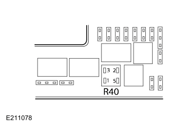 Washer relay, cavity 3
|
|
Ground
|
Are the voltages greater than 11 volts?
|
| N6 BYPASS THE HEADLAMP WASHER RELAY |
-
Connect:
|
Positive Lead
|
Measurement / Action
|
Negative Lead
|
|
Washer relay, cavity 3
|
|
Washer relay, cavity 5
|
-
Observe the headlamp washers.
-
Remove the fused jumper wire.
Do headlamp washers operate with the fused jumper wire connected?
|
| N7 CHECK THE HEADLAMP WASHER PUMP VOLTAGE SUPPLY CIRCUIT FOR AN OPEN |
-
Disconnect Headlamp Washer Pump C153
.
-
Connect:
|
Positive Lead
|
Measurement / Action
|
Negative Lead
|
|
Washer relay, cavity 3
|
|
Washer relay, cavity 5
|
-
Measure:
Click to display connectors
|
Positive Lead
|
Measurement / Action
|
Negative Lead
|
|
C153-1
|
|
Ground
|
Is the voltage greater than 11 volts?
| Yes |
REMOVE the fused jumper wire. GO to N8
|
| No |
REMOVE the fused jumper wire. REPAIR the circuit.
|
|
| N8 CHECK THE HEADLAMP WASHER PUMP GROUND CIRCUIT FOR AN OPEN |
-
Measure:
Click to display connectors
|
Positive Lead
|
Measurement / Action
|
Negative Lead
|
|
C153-2
|
|
C153-1
|
Is the voltage greater than 11 volts?
| Yes |
INSTALL a new headlamp washer pump.
|
|
| N9 CHECK THE HEADLAMP WASHER RELAY CONTROL CIRCUIT FOR A SHORT TO VOLTAGE |
-
Disconnect Windshield Wiper Motor C1655
.
-
Measure:
Click to display connectors
|
Positive Lead
|
Measurement / Action
|
Negative Lead
|
|
C1655-10
|
|
Ground
|
Is any voltage present?
|
| N10 CHECK THE HEADLAMP WASHER RELAY CONTROL CIRCUIT FOR AN OPEN |
-
Measure:
Click to display connectors
|
Positive Lead
|
Measurement / Action
|
Negative Lead
|
|
C1655-10
|
|
C1035B-22
|
Is the resistance less than 3 ohms?
|
| N11 CHECK FOR CORRECT WINDSHIELD WIPER MOTOR OPERATION |
-
Disconnect and inspect the windshield wiper motor connector.
-
Repair:
-
corrosion (install new connector or terminal - clean module pins)
-
damaged or bent pins - install new terminals/pins
-
pushed-out pins - install new pins as necessary
-
Reconnect the windshield wiper motor connector. Make sure it seats and latches correctly.
-
Operate the system and determine if the concern is still present.
Is the concern still present?
| Yes |
CHECK OASIS for any applicable Technical Service Bulletins (TSBs). If a
TSB exists for this concern, DISCONTINUE this test and FOLLOW the TSB
instructions. If no Technical Service Bulletins (TSBs) address this
concern, INSTALL a new windshield wiper motor.
REFER to: Windshield
Wiper Motor (501-16 Wipers and Washers, Removal and Installation). TEST
the system for normal operation. If the concern is still present, GO to
N12
|
| No |
The system is operating correctly at this time. The
concern may have been caused by a loose or corroded connector. ADDRESS
the root cause of any connector or pin issues.
|
|
| N12 CHECK FOR CORRECT SCCM (STEERING COLUMN CONTROL MODULE)
OPERATION |
-
Disconnect and inspect all the SCCM connectors.
-
Repair:
-
corrosion (install new connector or terminal - clean module pins)
-
damaged or bent pins - install new terminals/pins
-
pushed-out pins - install new pins as necessary
-
Reconnect the SCCM connectors. Make sure they seat and latch correctly.
-
Operate the system and determine if the concern is still present.
Is the concern still present?
| Yes |
CHECK OASIS for any applicable Technical Service Bulletins (TSBs). If a
TSB exists for this concern, DISCONTINUE this test and FOLLOW the TSB
instructions. If no Technical Service Bulletins (TSBs) address this
concern, INSTALL a new SCCM .
REFER to: Steering Column Control
Module (SCCM) (211-05 Steering Wheel and Column Electrical Components,
Removal and Installation).
REFER to: Steering Column Control Module (SCCM) - Vehicles With:
Adaptive Steering (211-05 Steering Wheel and Column Electrical
Components, Removal and Installation).
|
| No |
The system is operating correctly at this time. The
concern may have been caused by a loose or corroded connector. ADDRESS
the root cause of any connector or pin issues.
|
|
The Headlamp Washers Are Always On
Refer to Wiring Diagrams Cell 81 for schematic and connector information.
Normal Operation and Fault Conditions
REFER to: Wipers and Washers - System Operation and Component
Description (501-16 Wipers and Washers, Description and Operation).
Possible Causes
-
Wiring, terminals or connectors
-
Headlamp washer relay
-
Windshield wiper motor
PINPOINT TEST O: THE HEADLAMP WASHERS ARE ALWAYS ON
| NOTICE:
Use the correct probe adapter(s) when making
measurements. Failure to use the correct probe adapter(s) may damage the
connector.
|
| O1 CHECK THE HEADLAMP WASHER PUMP VOLTAGE SUPPLY CIRCUIT FOR A SHORT TO VOLTAGE |
-
Disconnect Headlamp Washer Relay.
Do the headlamp washers continue to operate?
|
| O2 CHECK THE HEADLAMP WASHER RELAY |
-
Disconnect Headlamp Washer Relay.
-
Substitute a known good relay.
Do the headlamp washers continue to operate?
| Yes |
REMOVE the known good relay. GO to O3
|
| No |
REMOVE the known good relay. INSTALL a new headlamp washer relay.
|
|
| O3 CHECK THE HEADLAMP WASHER RELAY CONTROL CIRCUIT FOR A SHORT TO GROUND |
-
Connect Headlamp Washer Relay.
-
Disconnect Windshield Wiper Motor C1655
.
Do the headlamp washers continue to operate?
|
| O4 CHECK FOR CORRECT WINDSHIELD WIPER MOTOR OPERATION |
-
Disconnect and inspect the windshield wiper motor connector.
-
Repair:
-
corrosion (install new connector or terminal - clean module pins)
-
damaged or bent pins - install new terminals/pins
-
pushed-out pins - install new pins as necessary
-
Reconnect the windshield wiper motor connector. Make sure it seats and latches correctly.
-
Operate the system and determine if the concern is still present.
Is the concern still present?
| Yes |
CHECK OASIS for any applicable Technical Service Bulletins (TSBs). If a
TSB exists for this concern, DISCONTINUE this test and FOLLOW the TSB
instructions. If no Technical Service Bulletins (TSBs) address this
concern, INSTALL a new windshield wiper motor.
REFER to: Windshield Wiper Motor (501-16 Wipers and Washers, Removal and Installation).
|
| No |
The system is operating correctly at this time. The
concern may have been caused by a loose or corroded connector. ADDRESS
the root cause of any connector or pin issues.
|
|
The Front Camera Washer Is Inoperative
Normal Operation and Fault Conditions
REFER to: Wipers and Washers - System Operation and Component
Description (501-16 Wipers and Washers, Description and Operation).
Possible Causes
-
Front camera washer hose or fittings
-
Front camera washer jet
Visual Inspection and Diagnostic Pre-checks
-
Inspect the front camera washer jet for damage
-
Inspect the front camera washer hose and fittings for damage
PINPOINT TEST P: THE FRONT CAMERA WASHER IS INOPERATIVE
| P1 CHECK THE WINDSHIELD WASHER OPERATION |
-
Momentarily activate the windshield washer function.
Does the windshield washer operate?
|
| P2 CHECK FOR WASHER SOLVENT TO THE FRONT CAMERA WASHER JET |
-
Disconnect the washer hose from the front camera washer jet and place it in a container to capture fluid.
-
Momentarily activate the windshield washer function.
Is washer fluid emitted at the washer hose?
| Yes |
INSTALL a new front camera washer jet.
|
| No |
REPAIR the front camera washer hoses or fittings as necessary.
|
|
The Heated Wiper Park Feature Is Inoperative
Refer to Wiring Diagrams Cell 81 for schematic and connector information.
Normal Operation and Fault Conditions
REFER to: Wipers and Washers - System Operation and Component
Description (501-16 Wipers and Washers, Description and Operation).
Possible Causes
-
Fuse
-
Wiring, terminals or connectors
-
Heated wiper park relay
-
BJB
-
Windshield
Visual Inspection and Diagnostic Pre-checks
-
Inspect BJB fuse 66 (15A) and make sure it is OK.
PINPOINT TEST Q: THE HEATED WIPER PARK FEATURE IS INOPERATIVE
| NOTICE:
Use the correct probe adapter(s) when making
measurements. Failure to use the correct probe adapter(s) may damage the
connector.
|
| NOTICE:
The following Pinpoint Test uses a test lamp to simulate
normal circuit loads. Use only a Rotunda Test Lamp (SGT27000) or
250-300mA incandescent bulb test lamp. To avoid connector terminal
damage, use the Rotunda Flex Probe kit for the test lamp probe
connection to the vehicle. Do not use the test lamp probe directly on
any connector.
|
| NOTE:
The heated wiper park does not operate at ambient
temperatures above 21° C (70° F). The following pinpoint test needs to
be carried out when the ambient air temperature is lower than 21° C (70°
F).
|
| Q1 CHECK THE REAR WINDOW DEFROST OPERATION |
-
Activate the rear window defrost feature.
Does the rear window defrost operate?
| No |
REFER to: Glass, Frames and Mechanisms (501-11 Glass, Frames and Mechanisms, Diagnosis and Testing).
|
|
| Q2 CHECK THE HEATED WIPER PARK RELAY COIL CONTROL CIRCUIT FOR AN OPEN |
-
Connect:
|
Lead 1
|
Measurement / Action
|
Lead 2
|
|
C1035B-21
|
|
 Battery Positive
|
-
Activate the rear window defrost feature.
Does the test lamp illuminate when the rear window defrost is activated?
|
| Q3 CHECK FOR VOLTAGE TO THE HEATED WINDSHIELD |
-
Disconnect Heated Windshield Element C1532
.
-
Connect:
Click to display connectors
|
Lead 1
|
Measurement / Action
|
Lead 2
|
|
C1532-1
|
|
Ground
|
-
Activate the rear window defrost feature.
Does the test lamp illuminate when the rear window defrost feature is activated?
|
| Q4 CHECK THE WINDSHIELD HEATED WIPER PARK GROUND CIRCUIT FOR AN OPEN |
-
Connect:
Click to display connectors
|
Lead 1
|
Measurement / Action
|
Lead 2
|
|
C1532-1
|
|
C1532-2
|
-
Activate the rear window defrost feature.
Does the test lamp illuminate when the rear window defrost feature is activated?
| Yes |
INSTALL a new windshield.
REFER to: Fixed Glass (501-11 Glass, Frames and Mechanisms, General Procedures).
|
|
| Q5 CHECK THE HEATED WIPER PARK RELAY OUTPUT CIRCUIT FOR AN OPEN |
-
Measure:
Click to display connectors
|
Positive Lead
|
Measurement / Action
|
Negative Lead
|
|
C1532-1
|
|
C1035B-5
|
Is the resistance less than 3 ohms?
|
The Heated Wiper Park Feature Is Always On
Refer to Wiring Diagrams Cell 81 for schematic and connector information.
Normal Operation and Fault Conditions
REFER to: Wipers and Washers - System Operation and Component
Description (501-16 Wipers and Washers, Description and Operation).
Possible Causes
-
Wiring, terminals or connectors
-
BJB
PINPOINT TEST R: THE HEATED WIPER PARK FEATURE IS ALWAYS ON
| NOTICE:
Use the correct probe adapter(s) when making
measurements. Failure to use the correct probe adapter(s) may damage the
connector.
|
| R1 CHECK THE REAR WINDOW DEFROST OPERATION |
Is the rear window defrost active?
| Yes |
REFER to: Glass, Frames and Mechanisms (501-11 Glass, Frames and Mechanisms, Diagnosis and Testing).
|
|
| R2 CHECK THE HEATED WIPER PARK RELAY OUTPUT CIRCUIT FOR A SHORT TO VOLTAGE |
Is the heated wiper park active?
|

.jpg) PINPOINT TEST S: WIPER BLADE PERFORMANCE CONCERNS - POOR CLEANING, STREAKING, OR CHATTER
PINPOINT TEST S: WIPER BLADE PERFORMANCE CONCERNS - POOR CLEANING, STREAKING, OR CHATTER
|
Normal Operation and Fault Conditions
Wiper blade cleaning, streaking, or chatter
concerns are commonly caused by dirt, ice, debris, or other foreign
material on the wiper blade(s) or glass surface. The wiper blades and
glass surface should be cleaned and retested prior to replacing wiper
blades for a cleaning, streaking, or chatter concern.
Possible Sources
- Dirt, ice, debris, or other foreign material on wiper blade(s)
- Dirt, ice, debris, or other foreign material on glass surface
- Damage to wiper blade(s)
- Damage to glass
Visual Inspection and Pre-checks
- Inspect the glass surface for damage
|
| S1 CLEAN THE WIPER BLADES AND GLASS SURFACE |
-
Clean the suspect wiper blade(s):
-
Wipe the suspect wiper blade(s) with a clean,
lint-free cloth and windshield washer fluid (Motorcraft ZC-32M20-EG or
equivalent)
-
Clean the glass surface:
-
Wipe the suspect glass surface with a clean,
lint-free cloth and glass cleaner (Motorcraft ZC-23 or equivalent)
Is the wiper performance concern still present (poor cleaning, streaking, chatter)?
| Yes |
INSTALL new wiper blade(s) for the blade(s) in question.
|
| No |
The system is operating correctly. The concern was
caused by dirt, ice, debris, or other foreign material on the wiper
blade(s) or glass surface
|
|
Disconnect
WARNING:
Before beginning any service procedure in this
section, refer to Safety Warnings in section 100-00 General Information...
Other information:
WARNING: It is extremely dangerous
to ride in a cargo area, inside or outside of
a vehicle. In a crash, people riding in these
areas are more likely to be seriously
injured or killed. Do not allow people to
ride in any area of your vehicle that is not
equipped with seats and seatbelts...
Checking the Tire Pressures
Safe operation of your vehicle requires
that your tires are properly inflated.
Remember that a tire can lose up to half
of its air pressure without appearing flat.
Every day before you drive, check your
tires. If one looks lower than the others,
use a tire gauge to check the pressure
of all tires and adjust if required...

 Washer Hose Coupling. General Procedures