Lincoln Nautilus: Body Repairs - General Information / Joining Techniques. General Procedures
Special Tool(s) / General Equipment
| Resistance Spotwelding Equipment | |
| Grinder | |
| Plasma Cutter | |
| Air Body Saw | |
| 8 mm Drill Bit | |
| MIG/MAG Welding Equipment | |
| Spot Weld Drill Bit |
Materials
| Name | Specification |
|---|---|
| Metal Bonding Adhesive TA-1, TA-1-B, 3M™ 08115, LORD Fusor® 108B, Henkel Teroson EP 5055 |
- |
| Seam Sealer TA-2-B, 3M™ 08308, LORD Fusor® 803DTM |
- |
| Motorcraft® Metal Surface Prep Wipes ZC-31-B |
- |
| ValuGard™ Premium Undercoating VG101, VG101A |
- |
| ValuGard™ Rust Inhibitor VG104, VG104A |
- |
Repair
NOTE: Weld Bonding - Squeeze-Type Resistance Spot Welding (STRW) Method
-
Refer to: Body Repair Health and Safety and General Precautions (100-00 General Information, Description and Operation)..jpg) WARNING:
Before beginning any service procedure in this
section, REFER to Safety Warnings in section 100-00 General Information.
Failure to follow this instruction may result in serious personal
injury.
WARNING:
Before beginning any service procedure in this
section, REFER to Safety Warnings in section 100-00 General Information.
Failure to follow this instruction may result in serious personal
injury.
-
Verify the vehicle is dimensionally correct on a frame machine. Straighten if necessary.
-
Remove damaged panels. Remove only large portions of the
damaged panel. Avoid cutting into mating flanges or adjacent parts.
Use the General Equipment: Air Body Saw
Use the General Equipment: Plasma Cutter
-
Drill out the spot welds and remove the remaining portions of the panel to be replaced.
Use the General Equipment: Spot Weld Drill Bit
-
Prepare any damaged flanges on the vehicle using hammer and dolly.
-
Grind the mating surface of the original flanges no
greater than 25 mm (0.9843 in) where the metal bonding adhesive will be
applied.
-
Be sure to remove galvanizing on metal. Metal should
have a shiny appearance. Be careful not to damage the corners or thin
the metal. The E-coat should also be removed on the opposite side of the
flange only where the spot welds are to be placed. Clean surfaces with
surface prep.
Material: Motorcraft® Metal Surface Prep Wipes / ZC-31-B
-
Dry-fit and clamp the replacement service parts to verify a correct fit.
-
Remove the service part after verifying correct fit and alignment.
-
Prepare the adhesive. Dispense a small amount of
adhesive from the cartridge to make sure of an even flow of both
components. Attach the mixing tip and dispense a mixing tip length of
adhesive to make sure of a correct mix ratio.
Material: Metal Bonding Adhesive / TA-1, TA-1-B, 3M™ 08115, LORD Fusor® 108B, Henkel Teroson EP 5055
-
NOTE: Welding can be carried out anytime during the adhesive curing process, or after the adhesive is fully cured. Welder settings will vary when welding through wet adhesive versus welding through fully cured adhesive. Refer to welder manufacturer's recommended settings for welding through fully cured adhesive. It is recommended to place a shunt weld in an area with no adhesive to make sure of conductivity, particularly when welding through fully cured adhesive.
NOTE: Refer to the product label for handling and preparation instructions.
Create a test sample.
-
Prepare the metal and adhesive as described. Apply a 6
mm (0.2362 in) - 9 mm (0.3543 in) bead of adhesive and weld the sample.
Use the General Equipment: Resistance Spotwelding Equipment
-
Place the welded sample in a vice and carry out
destructive weld tests by peeling the scrap metal apart using large
lock-type pliers. Measure the weld nugget to determine that the nugget
meets Ford weld nugget requirements. If the weld nugget does not meet
required size, adjust welder settings until the correct weld nugget size
is achieved.
Refer to: Specifications (501-25 Body Repairs - General Information, Specifications).
-
Apply a 6 mm (0.2362 in) - 9 mm (0.3543 in) bead of adhesive to the vehicle prepared flange surface.
-
Place the service part(s) in the correct position on the vehicle.
-
When positioned, do not pull the component away from
the vehicle. If repositioning is necessary, slide the service part(s).
This will make sure of correct contact between the components and
adhesive.
-
Clamp evenly and tightly. The adhesive contains glass beads which will prevent over-clamping the component.
-
NOTE: Refer to the product label for cure times and handling instructions. Clamps may be removed immediately after the component is welded.
Wipe excess adhesive from the panel before it cures.
-
NOTE: The ends of welding clamps should be insulated on the ends using tape or similar material when welding is carried out.
Complete the spot welding process following Ford recommendations and welder manufacturer procedures and settings.
Refer to: Specifications (501-25 Body Repairs - General Information, Specifications).
Use the General Equipment: Resistance Spotwelding Equipment
-
Finish any cosmetic section seams with fiber-filled body
filler. Rough sand the filler, apply conventional body filler after the
adhesive cures and block-sand the area.
-
Mix and apply primer surfacer per Ford-approved paint recommendations.
-
Seal wherever a cosmetic seam sealer is required.
Material: Seam Sealer / TA-2-B, 3M™ 08308, LORD Fusor® 803DTM
-
Refinish using a Ford approved paint system.
-
Refer to: Corrosion Prevention (501-25 Body Repairs - General Information, General Procedures).
Material: ValuGard™ Premium Undercoating / VG101, VG101A
Material: ValuGard™ Rust Inhibitor / VG104, VG104A
Repair
NOTE: Weld Bonding - Metal Inert Gas (MIG) Welding Method
-
Refer to: Body Repair Health and Safety and General Precautions (100-00 General Information, Description and Operation).
WARNING:
Before beginning any service procedure in this
section, REFER to Safety Warnings in section 100-00 General Information.
Failure to follow this instruction may result in serious personal
injury.
-
Verify the vehicle is dimensionally correct on a frame machine. Straighten if necessary.
-
Remove damaged panels. Remove only large portions of the
damaged panel. Avoid cutting into mating flanges or adjacent parts.
Use the General Equipment: Air Body Saw
Use the General Equipment: Plasma Cutter
-
Drill out the spot welds and remove the remaining portions of the panel to be replaced.
Use the General Equipment: Spot Weld Drill Bit
-
After removing the damaged sheet metal panel(s), repair
any damaged flanges on the vehicle using a hammer and dolly.
-
Using an appropriate grinder, carefully grind around the
entire receiving flange area following the original welds. Be sure to
remove all E-coat, paint or galvanized coating from the mating surfaces
of the joint.
Use the General Equipment: Grinder
-
Be sure to remove galvanizing on metal. Metal should
have a shiny appearance. Be careful not to damage the corners or thin
the metal. The E-coat should also be removed on the opposite side of the
flange only where the spot welds are to be placed. Clean the surface.
-
Repeat the procedure on the mating surface of the replacement service part(s).
Use the General Equipment: Grinder
-
Prepare the new service panel for plug welds.
-
Using the original panel as a reference, drill or punch
holes in the exact number as the original spot welds. The holes should
be positioned as close as possible to the original spot weld locations,
without lining up exactly on top of an original spot weld site. To make
sure of correct weld performance, grind the immediate perimeter of the
plug weld hole. Grind only in the area of the plug weld; this will keep
the potential of corrosion to a minimum.
Use the General Equipment: 8 mm Drill Bit
-
Clean all mating surfaces on both the vehicle and replacement panel.
Material: Motorcraft® Metal Surface Prep Wipes / ZC-31-B
-
Dry-fit and clamp the replacement service parts to verify a correct fit and alignment.
-
Remove the service part after verifying correct fit and alignment.
-
The vehicle prepared flange areas where plug welds will
be located must be kept free of adhesive. Apply 25 mm (0.9843 in) tape
to the plug weld areas to prevent contamination from the adhesive.
-
Prepare the adhesive. Dispense a small amount of
adhesive from the cartridge to make sure of an even flow of both
components. Attach the mixing tip and dispense a mixing tip length of
adhesive to make sure of correct mix ratio.
Material: Metal Bonding Adhesive / TA-1, TA-1-B, 3M™ 08115, LORD Fusor® 108B, Henkel Teroson EP 5055
-
NOTE: Refer to the product label for cure times and handling instructions.
Apply a 6 mm (0.2362 in)-9 mm (0.3543 in) wide bead of adhesive to the vehicle prepared flange surface. Remove the tape from the plug weld areas.
Material: Metal Bonding Adhesive / TA-1, TA-1-B, 3M™ 08115, LORD Fusor® 108B, Henkel Teroson EP 5055
-
Place the service part(s) in the correct position on the vehicle.
-
When positioned, do not pull the component away from
the vehicle. If repositioning is necessary, slide the service part(s).
This will make sure of correct contact between the components and
adhesive.
-
Clamp evenly and tightly. The adhesive contains glass beads which will prevent over-clamping the component.
-
NOTE: Welding can be carried out anytime during the adhesive curing process or after the adhesive is fully cured.
NOTE: If welding will not be carried out immediately, refer to product label for cure times and handling instructions. Clamps may be removed immediately after the component is welded.
Wipe excess adhesive from the panel before it cures.
-
Complete the plug-welding process following Ford recommendations.
Refer to: Specifications (501-25 Body Repairs - General Information, Specifications).
Use the General Equipment: MIG/MAG Welding Equipment
-
Finish any cosmetic section seams with fiber-filled body
filler. Rough sand the filler, apply conventional body filler after the
adhesive cures and block-sand the area.
-
Mix and apply primer surfacer per Ford-approved paint recommendations.
-
Seal wherever a cosmetic seam sealer is required.
Material: Seam Sealer / TA-2-B, 3M™ 08308, LORD Fusor® 803DTM
-
Refinish using a Ford approved paint system.
-
Refer to: Corrosion Prevention (501-25 Body Repairs - General Information, General Procedures).
Material: ValuGard™ Premium Undercoating / VG101, VG101A
Material: ValuGard™ Rust Inhibitor / VG104, VG104A
 Inspection And Repair After Collision Without Supplemental Restraint Deployment. General Procedures
Inspection
If airbags deploy.
Refer to: Inspection and Repair after a Supplemental Restraint System (SRS) Deployment (501-20B)
.
NOTE:
Deployable devices such as airbags, pretensioners and
inflatable belt inflators, may deploy alone or in various combinations
depending on the impact event...
 Plastic Repairs. General Procedures
Special Tool(s) /
General Equipment
ALCV-200
Materials
Name
Specification
Plastic Bonding AdhesiveTA-9
-
Inspection
NOTE:
Plastics Identification
WARNING:
Before beginning any service procedure in this
section, REFER to Safety Warnings in section 100-00 General Information...
Other information:
Lincoln Nautilus 2018-2026 Service Manual: Parking Assist Control Module (PAM). Removal and Installation
Removal NOTE: If installing a new PAM , it is necessary to upload the module configuration information to the scan tool prior to removing the module. This information must be downloaded into the new PAM after installation. Using a diagnostic scan tool, begin the PMI process for the PAM following the onscreen instructions...
Lincoln Nautilus 2018-2026 Service Manual: Headlamp Switch. Removal and Installation
Removal Detach the clips and pivot the instrument panel LH lower trim panel downward. Remove the headlamp switch. Disconnect the headlamp switch electrical connector. Release the tabs and remove the headlamp switch from the instrument panel LH lower trim panel...
Categories
- Manuals Home
- 1st Generation Nautilus Owners Manual
- 1st Generation Nautilus Service Manual
- Normal Scheduled Maintenance
- Changing the 12V Battery
- Auto-Start-Stop
- New on site
- Most important about car
Replacing the Rear Wiper Blades
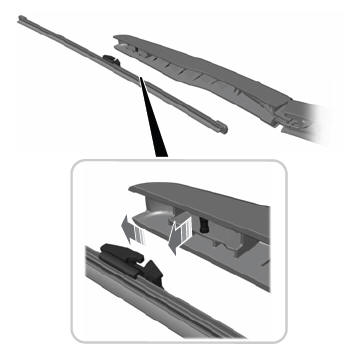
Note: Do not hold the wiper blade to lift the wiper arm.
Remove the wiper blade.