Lincoln Nautilus: Handles, Locks, Latches and Entry Systems / Rear Door Latch. Removal and Installation
Removal
NOTE: LH side shown, RH side similar.
NOTE: Removal steps in this procedure may contain installation details.
-
Remove the exterior rear door handle.
Refer to: Exterior Rear Door Handle (501-14 Handles, Locks, Latches and Entry Systems, Removal and Installation).
-
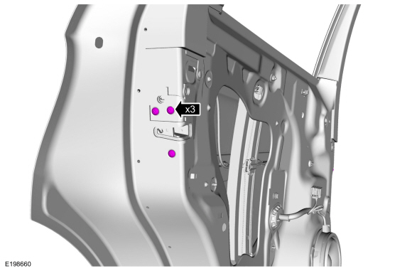
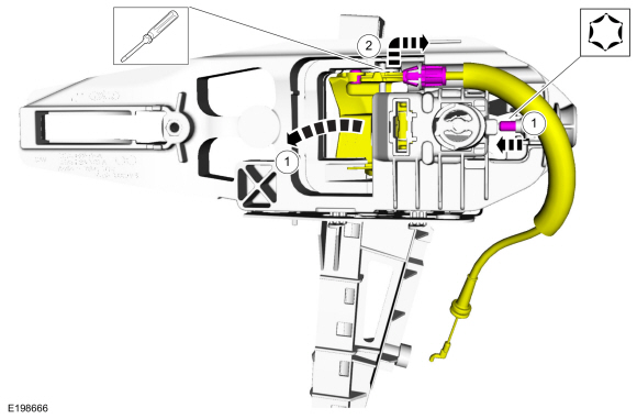
NOTE: The rear door removed for clarity.
Remove the exterior door handle reinforcement screw.
Torque: 62 lb.in (7 Nm)
.jpg) |
-
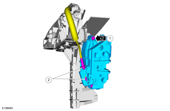
NOTE: The rear door removed for clarity.
Remove the rear door latch bolts.
Torque: 71 lb.in (8 Nm)
 |
-
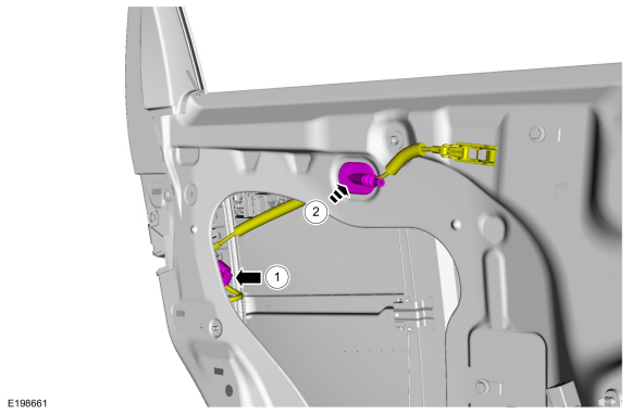
NOTE: The rear door removed for clarity.
Route the interior rear door handle cable through the door.
-
Disconnect the electrical connector.
-
Route the interior rear door handle cable through the door.
-
Disconnect the electrical connector.
 |
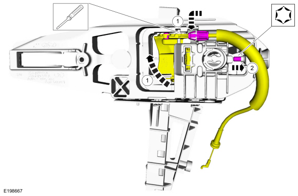
-
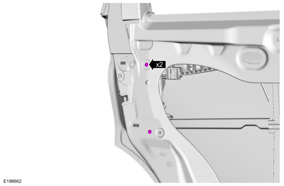
NOTE: The rear door removed for clarity.
Remove the retainers.
Torque: 19 lb.in (2.2 Nm)
 |
-
Remove the rear door latch.
.jpg) |
-
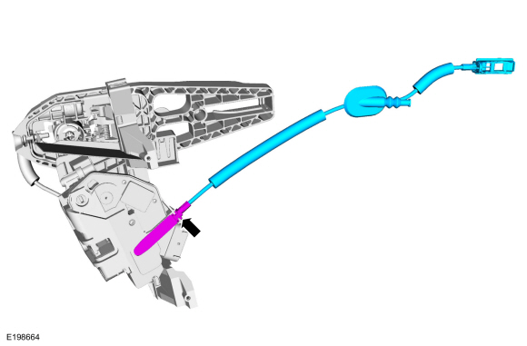
NOTE: This step is only necessary when installing a new component.
Remove the interior rear door handle cable from the rear door latch.
 |
-
NOTE: This step is only necessary when installing a new component.
Remove the exterior rear door handle reinforcement.
-
Tighten the screw to release the rear exterior handle actuation lever tension on the cable.
-
Detach and position aside the cable from the exterior rear door handle reinforcement.
-
Tighten the screw to release the rear exterior handle actuation lever tension on the cable.
 |
-
NOTE: This step is only necessary when installing a new component.
Remove the rear door latch.
-
Remove the screws.
-
Detach and position aside the cable from the rear door latch and remove the rear door latch.
-
Remove the screws.
 |
Installation
- To install, reverse the removal procedure.
-
NOTE: This step is only necessary when installing a new component.
Install the rear door latch.
-
Install the rear door latch and the screws.
-
Attach the cable to the rear door latch.
-
Install the rear door latch and the screws.
|
-
NOTE: This step is only necessary when installing a new component.
NOTE: This step must be done correctly or the exterior door handle will not engage the lever on installation.
Install the exterior rear door handle reinforcement.
-
Install the cable eyelet to the lever.
-
While keeping tension on the cable and holding the
handle lever in the engaged position, turn the release screw until the
handle lever is positioned against the stop.
-
Install the cable eyelet to the lever.
 |
-
NOTE: This step is only necessary when installing a new component.
Install the interior rear door handle cable to the rear door latch.
|
-
If the door is equipped with one touch up/down, carry out the power door window initialization.
Refer to: Power Door Window Initialization (501-11 Glass, Frames and Mechanisms, General Procedures).
 Liftgate Release Switch. Removal and Installation
Removal
Remove the reversing lamp.
Refer to: Reversing Lamp (417-01 Exterior Lighting, Removal and Installation).
Disconnect the liftgate release switch electrical connector...
 Remote Keyless Entry (RKE) Exterior Sounder. Removal and Installation
Removal
Remove the front bumper cover.
Refer to: Front Bumper Cover (501-19 Bumpers, Removal and Installation).
Remove RKE exterior sounder...
Other information:
Lincoln Nautilus 2018-2026 Service Manual: Audio Unit Antenna Cable. Removal and Installation
Removal NOTE: The original equipment body and liftgate audio unit antenna cable(s) are part of the wiring harness and cannot be removed. This procedure refers to replacement of the cable(s) only by overlaying the cable(s). NOTE: The instrument panel-to-body audio unit antenna cable inline connection is located under the floor console...
Lincoln Nautilus 2018-2026 Service Manual: Battery Monitoring Sensor. Removal and Installation
Removal NOTE: When the battery is disconnected and connected, some abnormal drive symptoms may occur while the vehicle relearns its adaptive strategy. The vehicle may need to be driven to allow the PCM to relearn the adaptive strategy values. NOTE: The cowl panel is removed for clarity only...
Categories
- Manuals Home
- 1st Generation Nautilus Owners Manual
- 1st Generation Nautilus Service Manual
- Anti-Theft Alarm System Settings. Security – Troubleshooting
- Engine Oil Capacity and Specification - 2.0L
- Massage Seats
- New on site
- Most important about car
Changing a Flat Tire
WARNING: If the tire pressure monitor sensor becomes damaged it may not function.
Note: The use of tire sealant may damage your tire pressure monitoring system and should only be used in roadside emergencies. If you must use a sealant, use the Tire Mobility Kit sealant. Replace the tire pressure monitoring system sensor and valve stem on the wheel by an authorized dealer after use of the sealant.
Note: The tire pressure monitoring system indicator light will illuminate when the spare tire is in use. To restore the full function of the monitoring system, all road wheels equipped with tire pressure monitoring sensors must be mounted on the vehicle.
If you get a flat tire while driving, do not apply the brake hea